|
The "Joe Rasmussen Approach to
Crossover"
[as it has been called
by some]
A HOLISTIC APPROACH TO
LOUDSPEAKER CROSSOVER DESIGN
(Holistic: The system as a whole determines
in an important way how the parts behave.)
April 2011 - Elsinore Mk5 & Mk6 - some details below are
obsolete.
The purpose below is not that of
preaching a subject, but to stimulate creative thought.
Every designer hones over a time a certain methodology
and years of refinement is the norm. The Crossover, as used and implemented in the Elsinore
Project, is likewise a result of many years of what might loosely be
called research (that seems to be a favourite term). But it basically comes
down to how you deal with a number of issues that are of primary and
secondary importance. To me the following are primary:
-
Summing 100% at All
Frequencies - 100% Driver Integration
-
An Alternative to
Butterworth and Avoiding its Failings
-
Butterworth and "Audio
Interruptus"
-
Analysing Mechanic &
Acoustic Limits Above Piston Range
-
Using The MidBass Driver's
Natural Roll-Off
-
Contour and Equalisation at
the Edges of Passband
-
Tweeter Hi-Pass - Single to
Multi-Order Transition
-
Tweeter - Maximising Voice
Coil Damping & Lower Distortion
-
Tweeter - Maximising Low
Order Power Handling
-
Impulse Response and
Electrical Phase Questions
-
Step Response & Time
Coherence Issues
-
By No Means a Complete
List...
Looking at the crossover of the Elsinore Project, it
seems quite simple. Yet that simplicity is quite deceiving. It deals with
some significant problems as used in multi-driver speaker designs. Behind
the Ellsinore's crossover is a highly defined methodology, one that needs
further explanation.
The following is not designed to be the final word in crossover design but
rather trying to explain an overall concept and a workable set of solutions,
and put them into a single package. There are arguably multiple approaches
to crossover design but just like all beers are either fundamentally ales or
lagers; there are single-order and multi-order crossovers.
As I am in the former camp I need to be more critical of driver selection as
they must behave more predictably at the edges of their passband. That term
needs explanation. All drivers are bandpass devices and their useable range
is the passband (or bandpass). Single (low) order requires drivers with
wider passbands as their behaviour above and below the crossover point (Hz)
is still contributing significantly to the summed response. The summed
response is when two or more drivers contribute to a flat response.
Next, our phase at the crossover must have complimentary phase throughout
the summed range, which means both below and above the crossover. This does
not happen by chance. What concerned Linkwitz and Riley in their 2nd and 4th
order crossovers was the acoustic phase at the crossover point should be the
same (not to be confused with electrical phase). We want this also to be the
case with 1st order designs. This also needs explanation as it is not
conventionally (and theoretically) true with respect to 1st order.
Butter Not Worth All it Seems?
Those interested in 1st order crossovers use
Butterworth filters, because of the claimed 'correct phase' and also when
taken to the very extreme, drivers staggered properly in time (so-called
time alignment) is able to produce either a single Stepped response and/or
square waves.
But these are Butterworth filters and they only sum the response half of the
time - which will be explained as we go on. This is why L-R filters are
minus 6dB when producing a flat summed response but Butterworth are only
minus 3dB. Butterworth have 90° phase shift at the crossover point
that prevents full summing (they are also incapable of
achieving a proper symmetrical polar response which is a direct result of
getting the phase right - another thing that concerned Linkwitz and
Riley). This will come back to haunt us at a later
stage.
Why does Butterworth only sum half the time? Because it is a fact that they
have a severe phase deficiency. Butterworth? Phase deficiency? How can you
say that? Surely this is Heresy!
It may be in some quarters and it should not be, as it will
act as a deterrent and we become inflexible, by which we cannot then observe the complete picture. Curious
fact: Butterworth filters sum flat whether or not the drivers are connected
in phase? This will be proved to be not such a good thing. Because of this 90°
phase shift they behave as follows.
Let's Start an Experiment:

Imagine two surfaces representing the two cones. The
grey line represents the natural resting point of the cone as well as the
box. Note there will be no output unless the cones actually move. Since this
is a Butterworth filter that precedes the drivers, the bottom driver is 90° behind the top driver.

The same signal is applied to both drivers. Here they
are both moving forward together. The top tier cone is now in the forward
position. The bottom driver has moved forward to the centre position. This
represents the first quarter of our cycle. Note the grey curve indicating
forward pressure. So during this quarter of a cycle the drivers are summing
(also angling down the radiation pattern that can prove another problem
to symmetrical polar response - but that is another subject).

Now something interesting has happened on our second
quarter of the cycle (each quarter represents 90°). The bottom driver
continues to move forward as in the previous quarter, but the top driver now
only has one way to move and that is backwards. It is easy to see that
during this quarter they are cancelling each other’s output. They sum zero.
In fact, at that moment there is no sound emanating at the centre of
the crossover frequency!
Audio
Interruptus?
On every second quarter of the cycle the speaker is
effectively dead at the centre frequency of the crossover - it is not just
reducing output but a total cancellation, zero output. This is
hardly desirable. Also cancels the off axis, exasperating that as a problem as
well, more about that later.
Let us continue:

Now both driver cones are moving backwards.
This time they cause rarefaction of the air, the air is moving in reverse as
we have reached minus 180°. They are summing (also
changing the angle of
radiation again and preventing that radiation from
becoming perpendicular to the front panel).

The final quarter is now obvious; the cones are doing
a switcheroo again and thus cancelling. We have returned to the original
state and the cycle is over. Once again, there is no sound emanating at
the centre of the crossover frequency!
So the sequence is sum, cancel, sum, cancel... etc. We are only summing
every second time (every second quarter of a completed cycle).
(Please see the explanation re
Angle of Radiation below.)
This is why higher order L-R filters were designed to
sum at the crossover point. At least they sum, sum, sum, sum etc, there is
no interruptus.
I showed the above example to a well known audio engineer and he was
astonished as it had never occurred to him. He could see now see that
Butterworth filters that sum acoustically (or at least supposed to) are
seriously flawed.
This 90° phase shift remains the same always whether connected
electrically in phase or not. Confirming this: Now try the same
experiment as above, but this time put the right driver ahead of the grey
line representing 180°. Instead of sum, cancel etc, it now becomes
cancel, sum etc. The summed response does not change whichever phase you
select. The net result is identical.
The following shows the phase response using a
Butterworth crossover @ 1KHz:
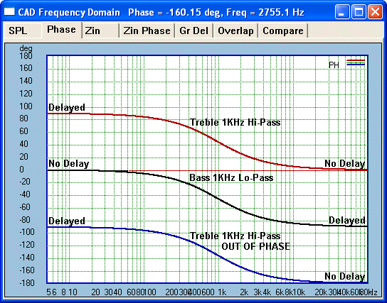
Please denote, filters (or crossovers) can only
delay. The Black Bass line (which is our reference here) starts to show delay as it gets closer
to the 1KHz crossover frequency. Relative to our reference Black Bass
line, we have two opposite Tweeter phase plots. The Tweeter
Red line, in phase, is not delayed at high frequencies. Note the 90°
split at all frequencies including the crossover frequency? Now note
the Blue line. It is the Tweeter connected
out of phase. Yet it is also split 90° at all frequencies including
the crossover frequency. So the difference phase sum is the same whether
Tweeter is in our out of phase.
Acoustically speaking, the error is always the same
and at all frequencies. It also explains why
Butterworth must be -3dB (only 50% summing). Of course, Butterworth constructors will stay with the in phase
and time align the drivers etc, but the problem remains. It is only
electrically in phase.
The above
plots does show that the error occurs at ALL frequencies, but the
effect of the filter's roll-off reduces the 90°
cancellations the further we get away from the crossover frequency. But the
error is always there.
Curiously, for a crossover that is famously supposed to be time correct, yet
the error is a constant at both sides of the crossover frequency and that
will prove very problematic in our discussion.
That it can still sum flat on axis seems good enough for the current
Butterworth purist, but the real problem is not on the on axis, the
severity shows up elsewhere.
The Real Achilles Heel
We need to discuss the real Achilles heel
of Butterworth. As we know that passband in the upper midrange change
drastically when comparing on and off axis responses. The off axis collapse, the
so-called beaming effect of midrange drivers. Here the incomplete summing
inherent in Butterworth is a severe limitation. We usually have wide
dispersion by the HF unit and we are now NOT taking advantage of that, even
denying it ability to actually helping solving the problem.
We are cancelling much of the
Tweeter's output where it is most needed, off axis. The beaming effect is
not fully filled in when it ought to be. In fact it is only half
filled at best.
Butterworth has poor Power
Response.
By getting the phase right we should sum correctly
over a much wider lateral area (filling in) and maintain good power response
because our off axis response is properly maintained. Good Power
Response is achievable. Butterworth is largely unable to do that. Remember
what we said earlier, the 90°
error isn't just at the crossover frequency, it dominates both below and
particularly above that frequency.
When two drivers behave well and consistent at below and above the crossover
point, on and off axis, then Butterworth filters only have one
drawback, wasted energy. So the low frequency crossover in 3-way speakers,
say around 300-600Hz, these can be Butterworth without much to trouble the
designer. It works because you have large overlapping passbands (and usually
well within their piston ranges). But
the upper crossover (and usually the only one in 2-way designs) we are
now working at the very edge of the midrange driver's passband.
Forget about whether the crossover is first order. It might be
'electrically' first order, but look at the on and off axis
and the power response of the raw driver will NEVER be first order. So much
for our beloved Butterworth theory, it just doesn't fit and worse, it
manages to get in the way. Do not get hung up about this or become a pursuer
of a lost [Butterworth] ideal.
As stated, we need another approach, one that is workable and consistent and
does not fight physics.
So this is the Introduction to a workable solution, the "Joe Rasmussen
Crossover” as named such by Brad Serhan of Orpheus Loudspeakers. It wasn't
me, but perhaps we should more accurately describe is as the "Joe Rasmussen
Approach to Crossover" - but we all do develop a methodology that suits us.
This work represents much effort from the mid-nineties until now. Much of it
by the seat-of-pants experiments, right through to correctly computer
modelling the result. These days I would not do a design without a strict
and disciplined approach, using computer capturing and modelling. It is all
explained here.
The Sum of It All? Getting it Together?
When we do design crossovers, we ought to keep our
eyes on the ball. It isn't just about flat frequency response at some single
discrete point in front of the loudspeaker.
Here a key word is summing. This incorporates not
just the target response being as flat as possible, but - here is another
key phrase - get the driver integration right and that means
getting the phase right. It must be right at a large range of
distances and maintained off axis. We need to gel
drivers together. We could call this the stitch between the drivers.
It must be predictable and not cause uncontrollable ripples in amplitude and
phase. Butterworth in the upper midrange always have difficulty in getting
the stich right.
Complete summing and driver
integration, a crossover not achieving this has failed.
A Problem Within a Problem?
Let us deal with yet another factor in making 1st
order crossovers difficult and hence why Butterworth is impractical. I don't
mind using Butterworth below 1KHz as often the drivers are not only in their
passbands but also likely to be within their piston range. This term also
needs explanation. Piston range is the range of frequencies where driver
cone moves as a whole, backwards and forward. Above a certain frequency
called the 'knee' by E. (Ted) Jordan, the response would drop by 6dB/octave
if the cone material were infinitely stiff (reputedly Allison did exactly that
back in the
70's). In order to extend response above the knee, the cone must start to
flex in such a way that the effective radiating area shrinks. In theory the diameter
of the radiating area should shrink and the area that shrinks should
continue to move as if it was a piston and the area out side, the cone area
nearer the edge, should be become stationary at those frequencies. In
reality it is not that simple, as the flexing of the cone cannot easily be
controlled in such a fashion. For those who want to look closer as to how
cones flex, see Martin Collom's High Performance Loudspeakers Edition
6, page 66.
Now we start to see the magnitude of a 1st order Butterworth Lo-Pass filter
for the midrange driver. The response beyond/above the knee is much less
predictable. Here is a basic rule I follow:
Below 1Khz it
is the diffraction loss (step baffle) that dominates, whereas the response
above 1Khz, it is the effect of the knee that is most
dominant.
Generally the former can be compensated by the usual
methods in the crossover as described by John L. Murphy and others. But the latter is far more difficult. Let me give
you a typical example of a Bass/Mid drivers response mounted in a box with
typical rectangular baffle.
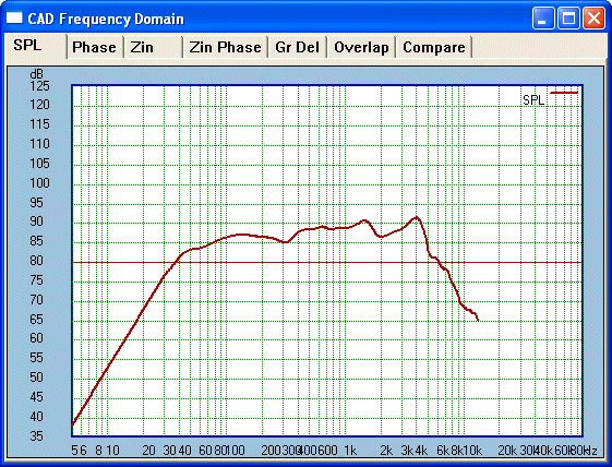
We can easily see the step baffle loss starting around
600 Hz. We can predict that after compensation it will average around
86-87dB sensitivity. So let us do that:
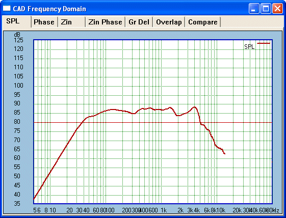
Not bad, we could have compensated slightly more. We
would expect this 6.5-inch driver to have acceptable piston response below
1500 Hz, roughly the knee frequency. But the elephant in the room remains
that large above the knee 4KHz peak (in many high quality drivers
even much worse again). Trying to roll this off will also magnify the trough
at 2KHz.
Close examination of the 4KHz peak showed something quite interesting. Is
this a cone break-up mode? Is there a prominent resonance behind this peak?
In this case and with this driver, the answer was no to both questions.
Waterfall plots and multi-harmonic distortion tests proved the driver was
largely clean.
So what exactly are we dealing with here? Well, if the problem is not
mechanical (cone break-up is mechanical), then we must look to the peak as
being an acoustic effect.
I am now touching in an area that I have not seen anybody write much about
before. It will lead to the correct answer because we are definitely
looking at an acoustic abnormality rather than mechanical failure. Take for
example the baffle step response below 1KHz, it is an acoustic effect. It is
not a mechanical failure of the box but rather an acoustic imprint because
of the shape of the rectangular baffle. We know we can compensate for the
step response in the crossover, then why not with the above knee response? I
see no reason why not.
Let us now consider how acoustically the response above the knee (rather
than a mechanical failure) affects the final response.
We can assume with reasonable
confidence that it is the shape of the cone that causes the 4KHz peak
rather than any break-up mode, of which it has already been cleared.
Reasonable confidence? Don't worry, let us see hard
proof.

Two drivers, both using the same chassis and magnetic
system and the same test baffle. Same test. Yet the cone material is
different but the cone profiles are almost identical. There is a
slight difference shown by the fact that the upper mid peak in the red
sample is narrower than the black, which has a concave dust cap just a
little smaller in diameter. But the cone materials are NOT the same! Just
very similar cone profiles. The approximate 1dB separation is because of
slightly different mass of the two cones, Red
higher mass than Black.
Note: It is the shape of the cones that matter, arguably also the frame and
cone terminations play a part too in shaping the acoustic response. Both
were clean from any major cone mechanical break-up modes, in fact top notch
performers.
Just as the step response is
a result of the baffle shape and dimensions, so too the response above the
knee is caused by diffraction effects largely within the driver.
There are two simple conclusions to be made:
Lynn Olson comments:
"I agree with Joe's comment these clean, well-defined peaks are not breakup[s],
but are artefacts of the cone shape itself. They are especially evident in
top-of-the-line cones with low inductance figures - in a more typical
high-inductance driver, the peak is intentionally masked by voice-coil
inductance. Since VC inductance is quite nonlinear, low inductance is a good
thing - but it does make the F[requency] R[esponse] look different than you
might expect." Read complete comments.
Esa Merilainen, Finland, has
also commented that there is a horn (or waveguide shape of most cones)
effect that also contributes to the type of peak seen above, and the effect
is not seen above a certain frequency, most notable in the 2-6KHz range and
by 10KHz typically finished, because of the natural roll-off.
Let us take a brief detour:
[Please note, from Elsinore Mk5
onward and including current Mk6, the LCR Trap near 4-5KHz is avoided for
reasons not covered here, but the acoustic phase EQ does provide suitable
insight.]
Equalisation in the
electrical domain will get rid of the wrinkles that shows up minimum phase
plots @ 4KHz - the amplitude response mirrors the phase response.
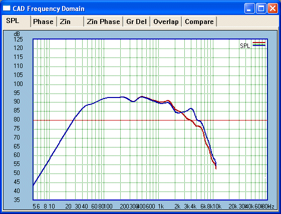
Here
Blue represents before EQ and Red post
EQ. Now what affect does this have on the minimum phase plots:
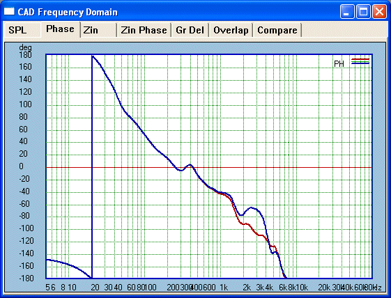
Identical plots, same colour
code. Post EQ Red cleans up both phase and amplitude.
It is much straighter and means our final crossover will track with greater predictability.
Adapt or Perish?
If cone break-up or mechanical integrity is not
compromised, why does the driver have to have a 1st order filter added? Does
it need it? This took me some time to absorb as it goes against what we
normally do. Sure, if it is a high order crossover, they do add a 2nd
, 3rd or 4th order low pass filter. But what we want is first order.
Again the fact we are dealing at the edge of the passband and above the
piston range, we need to be more adaptable in our thinking.
Our 4KHz peak (which we know we can EQ both amplitude and phase), and a
similar peak plague most mid/bass drivers. Just go on Tymphany's website and
look at drivers from Scan-Speak (expensive), Peerless and Vifa (now V-Line)
and at least some upper midrange peak is common, especially on axis and
sometimes ameliorated off axis. But with the right approach we can
overcome these.
Here is a suggested Lo-Pass (it is not really, but tradition dies hard) of
the above driver:
(OLD CROSSOVER TECHNIQUE)
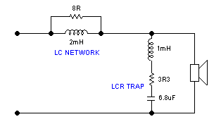
The LC Network is used to balance and flatten the
overall response including any necessary diffraction loss caused by the box.
The LC components of the LCR Trap is carefully tuned to the same frequency
as our peak, the Q decides the width of the peak to be dealt with, then the
resistive component applies the severeness and depth of the trap. With
careful adjustment of values we can tune out the peak and gain a smoother
and more rounded curve at the edge of the passband.
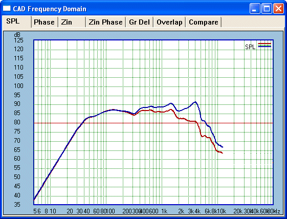
The Blue line is
our 'raw in the box' response and the Red
line after our so-called Lo-Pass filter has been applied. Look carefully at
around 7-10KHz and you can see the roll-off rate is virtually identical for
both plots. There is really no Lo-Pass filter as such, what we have done is
contoured our driver into a more desirable response. In fact the
crossover components are now really only equalisation components. We
can now concentrate on the Tweeter and crossover to match up with this
curve. The eye indicates that if we are to achieve full summing at -6dB,
then somewhere near 3Khz looks probable and acceptable.
Here is the result with Tweeter:
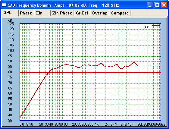
[In this example, I could have used a Tweeter with a smoother response.]
This happens to be the Peerless HDS 810921 and above is on axis. The approx
5-6Khz trough is partly common for this Tweeter (we will work on this later)
and the 16Khz peak reduces somewhat as you get off axis. I could have used
the Vifa XT25 Tweeter, which is smoother on axis especially, but the more
problematic HDS Tweeter sounds much better.
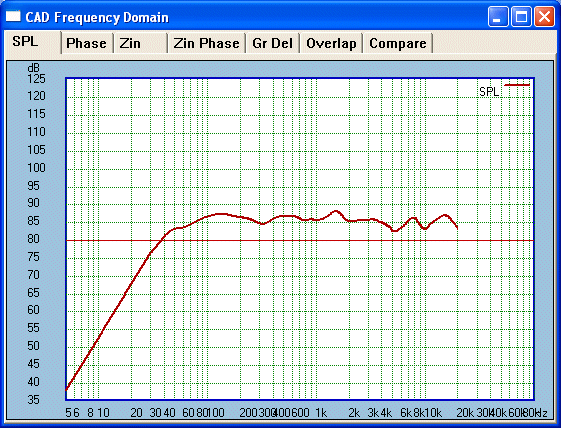
This is 15° off axis. The 5-6KHz dip is
there, but the overall response is smoother. Now let us get well off axis to
really test how things hold up:
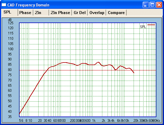
OK, what are we looking for? Obviously the top octave
and a bit is now down at 25° of axis. Note that the opposite response
will be the same so here we are looking at a total 50° arc in front of
the speaker. And the 5-6KHz is still a problem. But look at the response in
the critical octave 2-4Khz. Here the Tweeter is doing a remarkable job of
filling in for the beaming effect of the mid/bass driver.
Let us look at the split of the middle graph, 15° of axis:
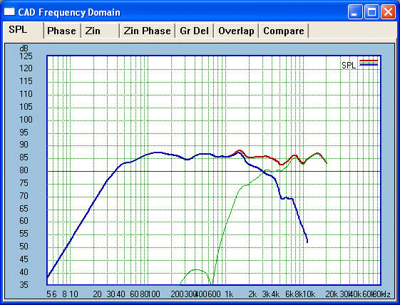
We can see that we are getting very close to 100% summing at 3Khz.
The summed response is exactly 6dB above the individual drivers output at
3KHz. Note that the crossover overlaps from 1Khz to almost 10KHz.
The crossover sums positive over
the whole overlap!
Hello? Now we can see that a combined response between
drivers around 5-6KHz is the cause of the dip, not the tweeter alone. We can
now further tweak the LCR Trap etc and see what improvement is possible.
The result is as follows:
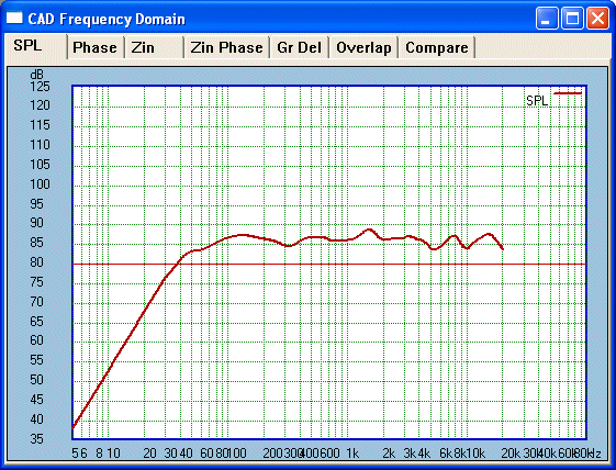
A reasonable improvement. This result is quite
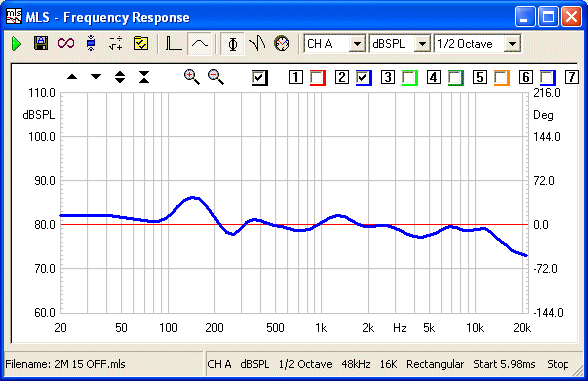
acceptable even if not perfect. The response is -/+ 2.5dB from well below 100Hz and 20KHz.
Moreover, the troughs and peaks average out well. There is a slightly less
than average output in the low treble range. This can be trimmed by ear
adjusting a single resistor in the High-Pass to the Tweeter.
The example shows the response with the Peerless HDS, but if the cheaper Vifa XT25
were used, the response would be significantly smoother. But the HDS's
upside is significantly lower distortion exchanged for flat response and
also much better off axis above 10KHz.
You Take the Low Pass and I Will Take the High Pass
[The LCR Trap above is avoided in Elsinore Mk5 and Mk5,
but the Null Trap below is still being used as it is out of band and below
1KHz.]
We now come to the Tweeter's High-Pass. This too has a few surprises.
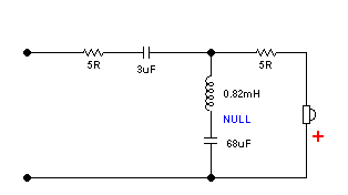
Please take the values as only indications. But it
does look rather simple and only a few questions will arise. But the
apparent simplicity disguises the complexities.
There is no doubt that some will have their attention brought to that
Red Positive. Yes,
it is connected electrically out of phase. But we shall see that it is in
fact acoustically in phase. Later, as we examine the
system impulse (step) response and minimum phase graph, we will establish
that the acoustic, and hence correct phase, is maintained up to 10KHz plus.
By that high frequency the overlap in the crossover is finished. We shall
also be able to produce square waves in the 500Hz-1KHz band.
But let us examine the amplitude response first. Note the two split 5R
resistors. In purest terms the second nearest the Tweeter should be omitted
but in computer modelling it was found to be useful. There is a null network
made from choke/capacitor series and then in parallel with the voice coil.
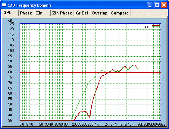
The pre and post null traces show that we have
maintained near first order down to around 1500 Hertz. The frequency and Q
of the null network has been carefully tailored to give the result shown.
The null frequency is clearly 650 Hertz, which coincides with the Tweeters
Fs. The choke DC resistance should be as reasonably low as possible, here it
is <0.5 Ohm and in this case we have achieved a very high order effect,
better than 5th order and close to 6th. The tailoring has given us low order
phase characteristics for an octave below the crossover frequency. This
should be a minimum.
The Peerless Tweeter now has very good power handling in comparison with
conventional first order. When we say 'power handling' in Tweeters, this
also equals low distortion.
Conventional odd order High-Pass networks have a common problem that 2nd and
4th orders does not. The problem is especially emphasised in 1st order. Let
us use the same Peerless Tweeter as an example, although other samples could
well be worse.
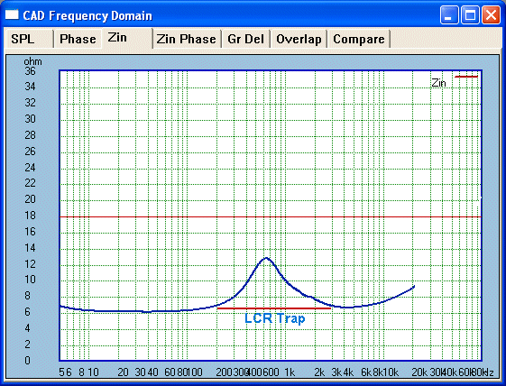
This is the raw impedance and the peak of 13-14 Ohm
indicates Fs equals 650 Hertz. Now let us put a single series cap for a
classic 1st order High-Pass. We can see that the peak is two times the base
line impedance; this will indicate a potential 6dB increase at 650 Hertz
unless we use an LCR trap to flatten impedance.
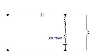
We shall see the results with and without LCR trap,
with or without flat impedance:
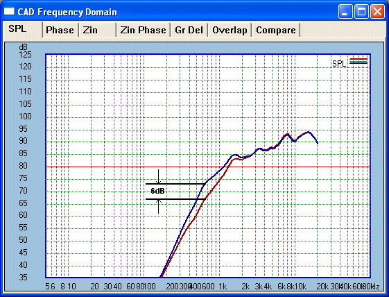
This example shows a single 3uF cap as the High Pass
filter, the Blue shows the response without any
impedance compensation. The 3uF cap is not rolling off at the full rate of
6dB/Octave. The Red line shows what it ought to
be when the filter is electrically 6dB/Octave. We then flatten out the 650
Hertz peak using an LCR trap. At the Tweeter's 650 Hertz resonance we have
an improvement of 6dB. That means the Tweeter's excursion is halved and the
actual heat dissipation is a quarter. That translates to lower distortion.
Tweeters as a rule do not like high amplitude motion.
The problem with Butterworth High Pass filters is that they leave the
Tweeter largely undamped at the Tweeter's resonance (in above case, the LCR
trap helps a great deal, but things could be better).
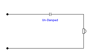
The reactance of the series cap in-creases
as the frequency descends.
Now compare 2nd Order:
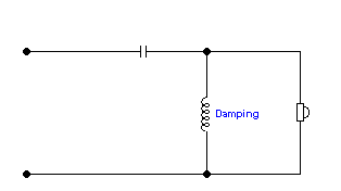
The reactance of the parallel inductor de-creases
as the frequency descends.
We won't show 3rd order (as 3rd order Butterworth),
but it suffers from the same as 1st order. What about 4th order:
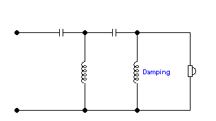
Again, as in 2nd order, the reactance of the final
parallel inductor de-creases as the frequency descends. This
coupled with high slope and the life of a Tweeter ought to be comfortable.
We can see the pattern, the final parallel inductor dampens the voice coil
where as a final cap reduces the damping. Generally 3rd order does better as
it does reduce amplitude, but again 1st order (they are all Butterworth)
needs some additional help, and the LCR trap is only a partial solution.
Here is our Final Solution (no pun intended):

Ignore the 5R resistors, here it is the Null that
interests us (and surprisingly the LCR works best when not directly across
Tweeter VC, if any series resistance is added). This is tuned to 650 Hertz and the peak of the Tweeter's
resonance. The inductor resistance needs to be as low as practicable. The
values are chosen to give the desired shape which is dictated by the Q of
the Null.
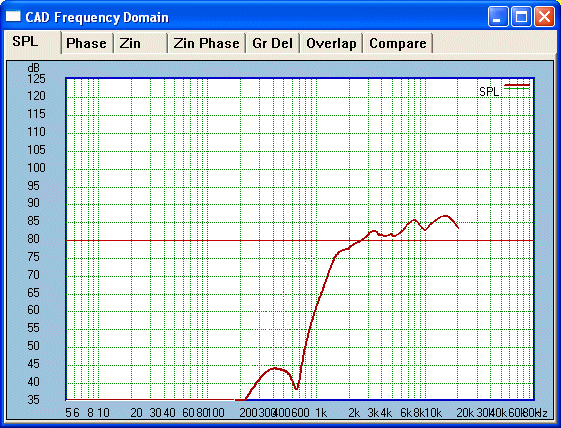
The final crossover and the Null is quite visible at 650
Hertz. Low order near crossover frequency and yet the Tweeter is well
protected. Distortion is low.
Looking In Time
Above section has been concerned what happens in the
amplitude/frequency domain. Before going on to the time domain I want to
make something clear first as it will make what follows (hopefully) easier
to understand.
We are all familiar with the sine wave, how it has a
plus and a minus part of the whole cycle. Something like this:
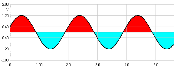
The Red represents
positive and Blue represents the
negative parts of the sine wave. This is a fine representation as at the
zero line there is no potential. But note we are thinking in terms of
potential (volts) here and that this representation does not hold true when
we enter the acoustic sphere.
Here we need to consider that it is not potential but
motion that is the key to understanding the sine wave.
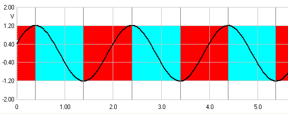
During the period (time) shown by
Red the sine wave is moving in a positive
direction even before it reaches the zero or median line. Same goes
for Blue except the movement is all negative.
Whereas electrically there is no potential when at zero, but acoustically it
is different. It is when motion ceases.
Keep this in mind: It
is the direction of movement that matters, not
where it is in relation to any zero line. This also applies to the time
domain, as will become clearer.
Summing It All Up - On The Step of an Impulse
This is what we are going to do: To get the drivers to integrate at the listening
position, they must ideally sum 100% at that point. Since the Tweeter will go
negative (for reasons that will become apparent) and the MidBass driver will go positive, the negative going part
of the Tweeter must occur before the onset of the positive pulse from the
midrange.
Here is a key thought, at some point the Tweeter's negative
impulse peak will be reached and at that point the Tweeter's output turns
positive. It will start to sum positive with the MidBass at that point,
provided they are correctly aligned in time. It is in fact only the first
half of the impulse response that the Tweeter cannot sum and does not
need to.
Now this part of the Tweeter's negative going pulse will equate to above
10KHz (high rise time and well above the crossover overlap) and makes it
possible to reverse the Tweeter's electrical phase and yet match the phase
of the midrange driver concurrently.
To make this possible the Tweeter must be time aligned specifically to line
up the two impulses. At no point must the two impulses work against each
other. As the negative going part from the Tweeter progresses there must be
no output from the midrange. If this is confusing, please read on and the
explanation should become clearer.
First step is to look at typical examples of the step response of individual
drivers and how we can line up the time factor.
Tweeter first:
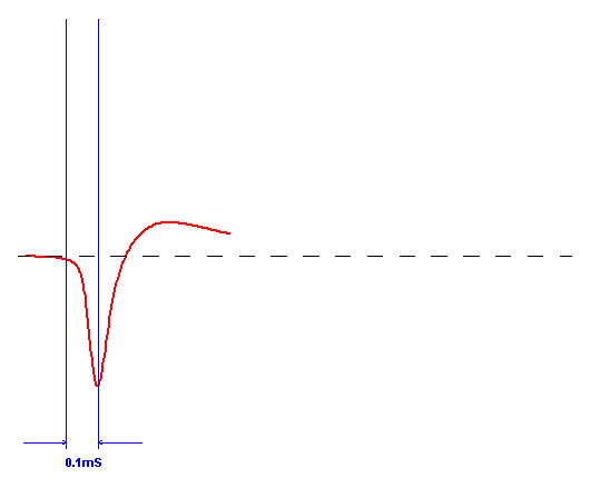
The Tweeter's electrical phase is reversed. The
negative pulse means the dome is moving inward (we keep it simple even if it
isn't, for clarity's sake). At a certain point it comes to a stop. As this
is a step response and if DC is seen by the Tweeter's voice coil, the dome
will be kept in that state (but in reality it doesn't as there is a Hi-Pass
filter function). At this point the pulse has to die, as there is only an
acoustic output when the dome actually moves. The air stops. The step
response reverts to positive phase (caused by natural air pressure) as it is
coming from a negative base, from which it can only go positive. The
position of the dome has little to do with it. Naturally, in real life the
Dome does return, as it does not see DC.
This may be difficult to wrap one's head around, but in reality it is quite
simple. Therefore the impulse/step response looks as above.
Here is a primary rule: It is
not where the impulse "is" but where it is going that interests us. That
movement is either positive or negative (no movement equals no output). So
the question is, is it going up (positive) or going down (negative)?
That means that the lateral broken line should not be
considered a zero reference point, only as a starting point. The Tweeter's step
goes negative for less than 0.1 microSecond, then all the rest of its useful
output is positive. It is the Tweeter's reverse acoustic phase that dominates
the total output in the
end. Surprised?
Now for the MidBass:
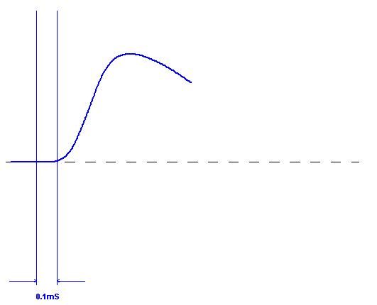
Here we have delayed the starting point of the step
response to coincide as closely as possible at the end of less than 0.1
microSecond so the Tweeter's output is not cancelled. Note the slower
rise time (if it had fast rise time we wouldn't need a Tweeter). The
positive going portion of the Tweeter's output will augment and increase
this rise time by summing correctly. The MidBass must go up (positive) at
the same point in time that the Tweeter does as well.
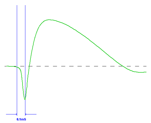
This is the combined step response. The rise time has been
maximised. Now for a look of all them overlayed:
It is important to grasp
that the step goes positive after 0.1uS and well before it gets to
the dotted median line. The rule is not where the pulse "is" but where it
is going.
The superimposed overlayed family that makes up the
whole:
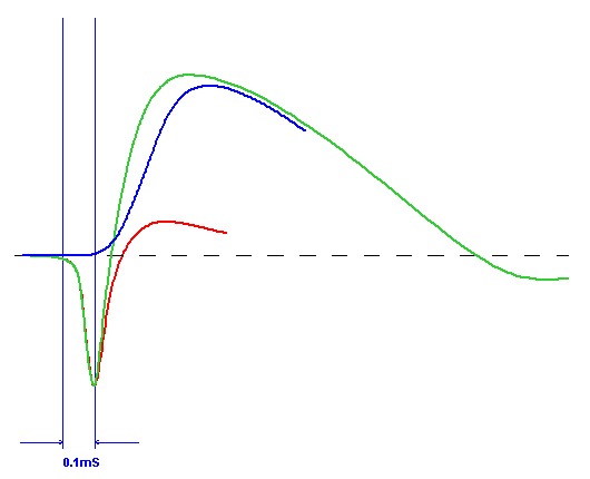
Can we see how this all fits together into a careful
scheme of things? After the Tweeter's initial 0.1 microSecond fast rise (of
which we are taking fortuitous advantage), all the drivers sum
positive and together.
(Note that the slower rise time of
the mid/driver Blue indicates that physical
alignment of the driver array is also much less critical and that it
will sum over a greater length or depth; it be less focus critical.)
Now that is the theory, let us look at the final
result:

The Red is the Tweeter's
Step Response and the Blue is the MidBass.

Here Green is the Total
Summed Step Response. I have left the Tweeter's in Red
to show that it is syncing perfectly.
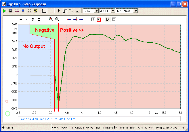
The total step response it is overwhelmingly
positive even if the Tweeter's electrically is out of phase. Note
where the positive Step Response starts. It starts at the bottom of the
inverted peak and not the zero line.
The Tweeter's output, even if it
is negative electrically, sums positive!
We can determine that the negative going part of the
Tweeter's impulse takes about 0.06mS - so our calculation:
1 / 0.00006 = 16 KiloHertz
The reverse polarity only shows up well above 10KHz,
below that we have perfect phase behaviour including 100% summing and driver
integration (by 10KHz the 3-4 KHz crossover is no longer overlapping). No
Butterworth 90° misbehaviour, good Off Axis augmentation preventing
beaming and ensuring flat power response as well as flat frequency response.
These are (but only) the highlights of the Elsinore Crossover. It looked
simple on the surface but 'under the bonnet' look tells a more complete
story.
Study the following graphs closely as they show how
the whole picture hangs together, not just in the frequency domain but also
in the time domain.
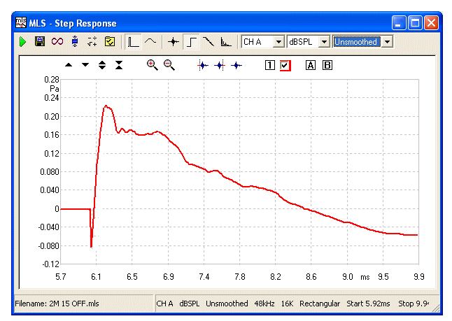
Final Step Response, also captured at 2 Metres and 15° Off
Axis

700 Hertz square wave captured at 2 Metres and 15°
Off Axis
IIn 3-Way speaker systems we
can use Butterworth Crossover between Bass and Midrange drivers, as there
will be no off-axis issues below 1KHz. In the crossover from the Midrange to
Tweeter use the method discussed here and we maintain the ability to
produce correct Step Response and Square Waves as per 2-Way example
shown above. This also applies to the 2½-Way Elsinores.
Mission
Accomplished!
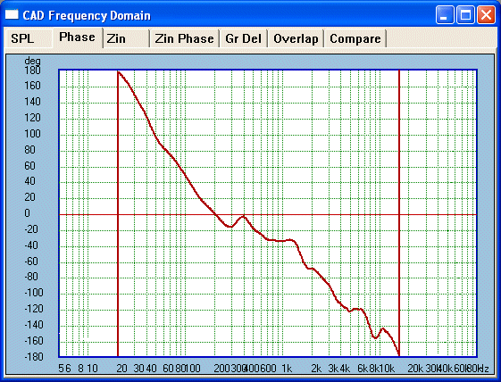
Minimum Phase is maintained from 20 Hertz to 16 KHz.
This indicates that the negative going pulse lasted
about 0.06mS - just as was indicated above.
Note Red Line is
0° - actual
Clio phase capture @ 2Metres & 15° Off Axis
(Sub 200 Hertz not considered accurate)
Here ends our journey for now. We have not crossed all
the T's and dotted all the I's. I am aware that the above needs to be read
several times for a total picture to emerge and then the dots will connect
themselves.
But we have given a significant insight to a
methodology that not only works but can be applied consistently over many
designs. So until next time, Arrivederci!
(Rev 1.0)
Joe Rasmussen
Explanation of Angle of
Radiation: Please note in the above Piston movement illustration that
the Angle of Radiation is perpendicular to the line that can be drawn from
the centres (nominally the acoustic centres or AC) of the two
Drivers. This mean that the Butterworth radiation pattern will never go straight ahead
which is perpendicular to the Front Panel (and likely aimed at the listening
position). It will either point above or below depending on piston movement
going in or out alternatively.
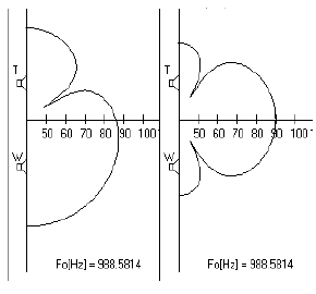
(Reference: John
Kreskovsky)
This asymmetrical lobing (on the left) cannot be eliminated in
Butterworth designs, it is a byproduct of the 90°
error associated with Butterworth 1st Order (note: Left, the straight on
axis is -3dB relative to 100% summing at 90dB on the Right). Time alignment of the two
Driver ACs with regard to the listener's position is not a solution. The
Pistonic example above does have the ACs time aligned with the
listener and yet exhibits the problem. Re-jigging it will always be a
compromise.
Addendum 2016: It should be noted
that the relative location of the crossover, taking in the offset between
the drivers (caused by the front panel and the location of the Voice Coils
of and within the respective drivers), that reversing the physical phase in
fact lessens that offset. Whatever the situation in most cases, the lobing
will be reduced.
The topic is far from being
exhausted.
Copyright © 2007-2017 Joe Rasmussen
|