|
LESSON - DON'T CHASE ACOUSTIC CENTRES
And Don't Waste A "Window of
Opportunity"
When adjusting the time alignment of 1st order arrays,
clearly we need to use some form of "stepped baffle"
- and there is no doubt that some physical re-alignment of the Tweeter is
required, via a stepped and sloped front panel.
This is often spoken of in terms of lining up the
Acoustic Centres (AC) of the drivers. But it is very difficult to determine
just exactly what is the AC of any particular driver. Nominally it should be
the centre of the Voice Coil, but in reality it may well change constantly
with frequency and dynamics and external factors like crossovers.
Let me say at the outset, it is only looking in time that
a proper physical alignment can be achieved and that will rarely be
coincident to any nominal AC of the driver. Even Dunlavy followed this rule that time does not lie, even if he didn't
express it exactly this way, but in speaker measurements it is true. You
have to look at
events as they happen.
I want to touch on things that are not yet spelt out on
this website before, re our approach to 1st order, and this would be a
good opportunity to share my thoughts with you.
So here goes - hope I don't sound too wordy:
I've mentioned often that Butterworth really has a very narrow window at
which the array can be focused. It really tries to approximate a point
source and at only one
discrete point in space in front of the loudspeaker. The thinking is to line up the Acoustic Centres (AC) via a
stepped baffle, but this "lining up" is actually a bit of bunkum. Lining up ACs
is really like chasing the wind, very futile.
Another approach to be
discussed here: Instead of lining up Acoustic Centres, the better approach
is to line up the Pulses of the Individual Drivers.
With this in mind, now look at the combined step response
generated by a 2-way system, Vifa C17 and Monacor DT-300 waveguide - a design
by Troels Gravesen. You get this
result by lining things up in time, not by lining up the ACs.
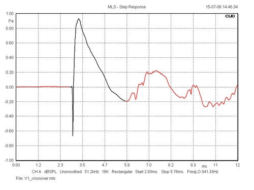
(Above borrowed from
Troels Gravesen)
This is a step response of a combined 2-way system. If you were to plot the drivers separately,
MidBass
and tweeter (with crossovers in place). You would note the tweeter goes
negative in an absolute explosion in time. Full acceleration that actually
defines its upper bandwidth.
After that very short burst the output goes entirely positive as Tweeter is already
inverting phase from the bottom and going up (positive) from the inverted peak. This we already
know... but other things gradually came to light.
Let's look at an instance where we are not looking at the
combined step response of two drivers as above, but an example where we have
separated the Tweeter (Red) and the MidBass (Blue):

Now, and this is where it gets interesting, look at the
Midbass Blue, and where the Tweeter
Red is negative in a burst of output activity,
the MidBass step response starts up very gradually and slowly in the
opposite phase. It is sluggish. The Tweeter
Red on the other hand is very fast.
Since the Tweeter's electrical phase is reversed, then it actually only
follows the electrical phase for a short period of time (and only at very
high frequencies). At normal frequencies, the Tweeter is acoustically
inverted.
In time (laterally on our graph), the point at which the
Tweeter Red sharply goes positive, this must
coincide somewhere in the area (in time) where the rise time of the MidBass
is slow. Here is our "Window of Opportunity" - and it is much wider
and more practical than anything conventional Butterworth 1st order can
achieve (I thank you Troels, for using that phrase first).
Now see if you follow me. Since we have this "Window of
Opportunity" in time, the slow rise of the Midbass
in the critical area in time where you are attempting to line up the
drivers, and while we may still focus at a critical spot
a la Butterworth, the physical window that results is much wider and
also less critical. Being less critical also means more acceptable results
even when we are not right in the centre of what is ideal.
This slow MidBass activity has a significant affect on how we step
the baffle rather than chase ACs. And that news is all good.
When we are discussing stepped baffles, we are actually
discussing the offset of drivers rather than any acoustic centres.
This is much more helpful. We still need to find an acceptable offset, but
it does not need to be millimetre accurate as it is far more forgiving.
But there is another interesting
feature that affects acceptable time alignment. For example, in the above
example it becomes apparent that the Tweeter can be mounted somewhat
further forward than otherwise. This decreases offset.
This too is a good thing as we shall see.
Look at the physical aspect of
a stepped baffle, or the "offset"
getting deeper into the front panel (or sloping it). What we are aiming to
do is accurately set the offset needed to be in time. With Butterworth type first order you have to choose an array focus point and
line things up extremely carefully and accurately. There is little
or no Window of Opportunity, you either get it right or you don't.
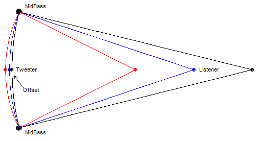
So this is quite obvious. We can see that if the
"Listener" is at infinity, the three drivers end up in a single plane, a
straight vertical line. But as we get closer to the driver alignment, the
physical offset of the Tweeter needs to be exaggerated. Whereas, if we go
further away, the alignment needs to be compressed.
But if we are able to minimise the
offset by being able to mount the Tweeter further forward,
then it can be seen that this compression and exaggeration is greatly minimised.
This is even more obvious as we go off axis.
Here
we will cause a compression of the alignment while the "Listener" position
remain unchanged. Suddenly the array will be focussing behind the
Listener.
By the time we get to 90 degrees
and side on to the front panel, the offsets have compressed into a single
plane and will focus at infinity.
Even at much less than 90 degrees we are seriously compressing the
stepped function of the front panel in time.
Go 45 degrees off axis with
Butterworth, and the focus point has disappeared into the next room.
With Butterworth, you cannot focus off axis!!!
A flat front panel only
focuses at infinity, indeed as we move side ways the alignment starts to
focus further and further away and eventually infinity.
But with our new approach, because the offset is smaller
than conventional Butterworth, when we go off axis, there is far less
compression of the offset between the drivers. This means, compared to
Butterworth where any off axis listening the array focuses further and
further away, with our new approach the focus point still goes outward, but
to a much less degree.
The same goes when we listen to it as we get closer
to the speaker. The required offset now become exaggerated, but nowhere to
the same degree as Butterworth. This is because the start of the various Radii was larger to
start with - and the larger the Radius is in the optimal focus point, the
less it will change proportionally if there is any error.
So the "Window of Opportunity" is just laterally but also
in the distance of the listener's position relative to the speaker but also
height.
The larger
offset Radii of Butterworth alignments leads to the same offset compression in the
vertical axis. So height sensitivity is lessened as well.
So we can clearly see that the
"Window of Opportunity" is a larger 3D window!
Think of Butterworth as a window no larger than your
head, but using The Renegade Tweeter Theory" we get a larger 3D rectangular
window and yet also all the benefits of Butterworth up to 15+KHz and non of
the less desirable problems.
I hate to sound preachy, but 1st order Butterworth simply
is not worth it - and I am speaking as a 1st order fan. As stated elsewhere
on this website, Butterworth works fine when both drivers at the crossover
frequency are working in their proper piston areas. Above 1KHz this becomes
near impossible when designing 1st order filters. Here the MidBass starts to
behave like LR2 off axis and starts to cancel out the Tweeter's output so
that it cannot fill in the eroding off axis response of the MidBass.
The MidBass is largely 1st
order on axis and LR2 off axis.
With our alternative approach we have 1st order crossover
that sums 100% at -6dB. The on axis crossover has a reasonable chance
of mimicking 1st order, but once we go off axis, think of the MidBass as LR2
and the Tweeter as 1st order. Because we have 100% vector summing at the
centre of the crossover frequency, the error is the same across the whole
system. Now I realise this is difficult to grasp, but this is indeed also
the case with Butterworth 1st order. The 90° phase error
inherent in Butterworth also stays constant across the whole bandwidth and
not just at and near the crossover:
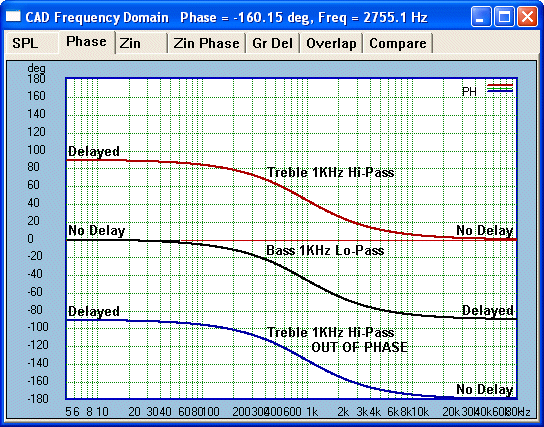
This makes clear the nature of the 90°
phase error inherent in Butterworth. Even though this example is 1KHz, the
relative error between the drivers is always there.
But eliminate it and you eliminate it across the whole
bandwidth. This applies to 1st order (our alternative)
and also LR2. So if we go LR2 from the MidBass when going off axis, the
Tweeter remains 1st order. Provided the error is near nil at the centre of
the crossover, then looking off axis and the Tweeter can fill in the LR2
without any interference and as the are both going in the same positive
direction with the Tweeter dominating all the more, whereas the MidBass is
failing, this means that the Tweeter will indeed dominate and
nominate the phase:
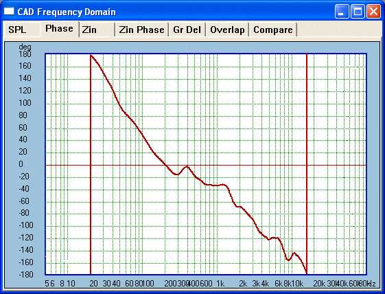
Here minimum phase is up to 16.5Khz
with 4 watt stimulus, indeed it is 23.5KHz with 1 Watt.
Here is an actual measured 700 Hertz
square wave:

Finally, this is the actual measured absolute phase
above 200 Hertz:
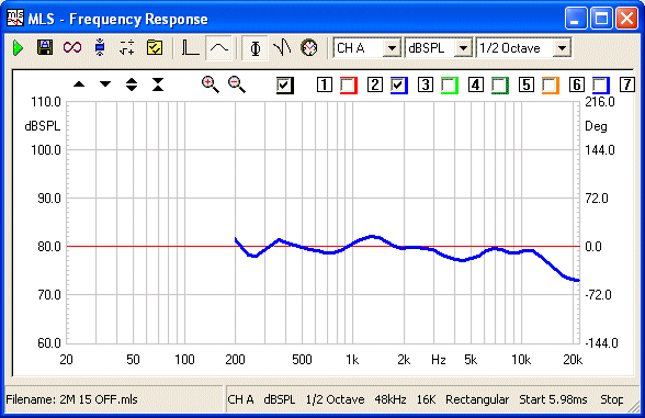
NOTE: THE ABOVE ARE ALL OFF
AXIS EXAMPLES!
Those results are entirely convincing. The subject is
anything but exhausted by the above, this is a multi-faceted topic and there
are many ways at looking at above, and the more we look at it, the more
things reveal themselves.
While speakers will always have a focus point a la
Butterworth, the real advantages go well beyond that. It isn't about more
persons able to fill the room and hear the speakers, although that is nice.
Still the person who sits in the "hot spot" will hear a far superior results
than would otherwise be possible, such as correct focus, image size and
image stability. Indeed, get it right and some have commented that in the
right set-up the speakers sound virtually 3D like, but from only two sources
and no added electronic gimmickry.
Joe R.
|