Normally, you present your case and then get to
the punch line. But to set the scene I am going to do it the other way, so
here it is:
The Tweeter's acoustic phase
is the opposite to the Tweeter's electrical phase. There is a precise 180°
relationship.
The faster the
Tweeter's rise time, the greater this scenario as the
perfect Tweeter has an Infinite Rise Time.
A Tweeter with an Infinite Rise Time has
all its useful acoustic output inverted.
The controversy
here is the
clear inference of those three statements is that we need to connect the
Tweeter in the electrical negative phase to optimise the acoustic phase.
If indeed we want to design linear or minimum phase speakers, especially
with a controlled Step Response etc, this ought not to be ignored. Indeed in
any design needs at least to be considered.
Reverse the phase to the
Tweeter?
Exactly. I don't expect you to accept this argument without
sufficient proof. Indeed I need to make a good case and I believe I can. It
can then be deduced that we need a fundamental change in approach and
assumptions.
A Paradigm Shift
is required.
Take The
Leap
Back To Basis
In Chapter 17 where we described a
holistic approach to crossover design, many have noted the out of phase
Tweeter connection. They believe I have not optimised the Tweeter's phase,
when in fact I believe I have. I received a number of
heated emails that pointed to the reversed electrically connected Tweeter in
the Elsinore speakers. How could I possibly make the claims I made when it
was electrically reversed?
(Edit: Thankfully this article
has stemmed the tide.)
This Chapter is really an addendum to
Chapter
17.
Let us reiterate a few things from
that chapter.
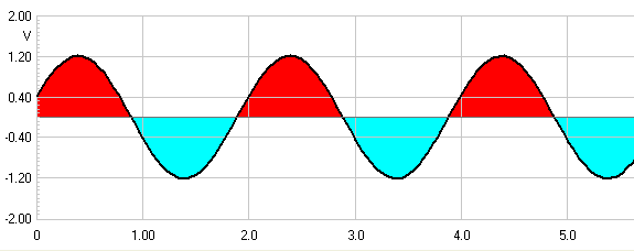
Here we have the traditional view of electrical phase.
During the Red half of the cycle we have
current flowing in one direction and during the negative
Blue, the opposite current flows.
But when we come to acoustic phase in motion, things are
decidedly different:
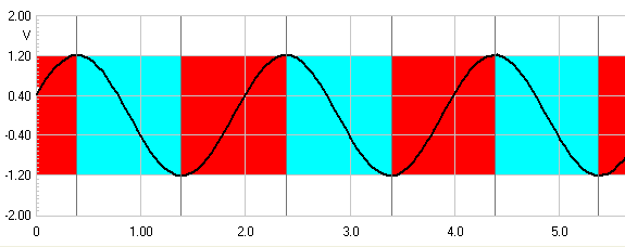
No movement, no output. So when motion is upwards in
the Red zone, then the acoustic phase is
positive and vice versa. So the transitional point is not some notional zero
point (the zero volt median line as in electrical phase) but at the point
where the change in motion takes place. Please keep this in mind as we shall
revisit. Note also the not inconsequential shift in time when an acoustic
sine wave is looked at in this light.
Because a sine wave only shows what happens at a
single discrete frequency, let us now examine some basic characteristics of
square waves. If you are advanced, let others absorb the subject.
Square waves shares one thing with sine waves, they
have a frequency, so many cycles per second. But a perfect square wave
encompasses an infinite number of frequencies. We shall attempt to explain.

Here we have a dead flat frequency response of a DUT.
This is an acronym for Device Under Test. It can be a loudspeaker, but it
would be unlikely to be that flat. More likely to be an amplifier. So what
happens if we put a 1KHz square ware through our DUT? Something like this:
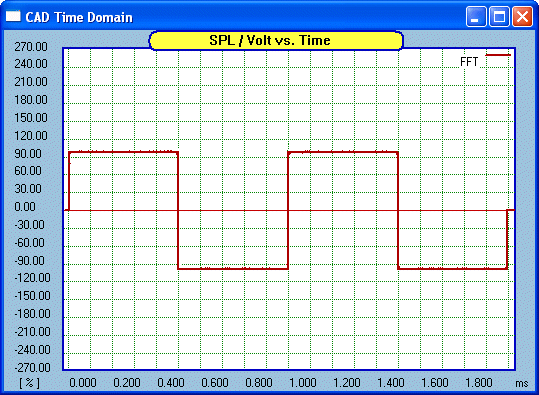
Nice and square. Let us now change our frequency
response and see what effect this has on our square wave. Let us see what a
treble boost does:
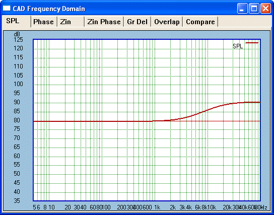
Now for our matching square wave:
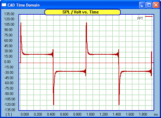
Whoa! The leading edge has been emphasised.
What about Treble cut:
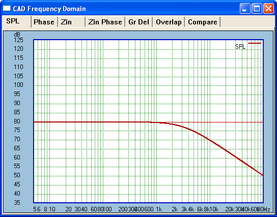
Now for our matching square wave:
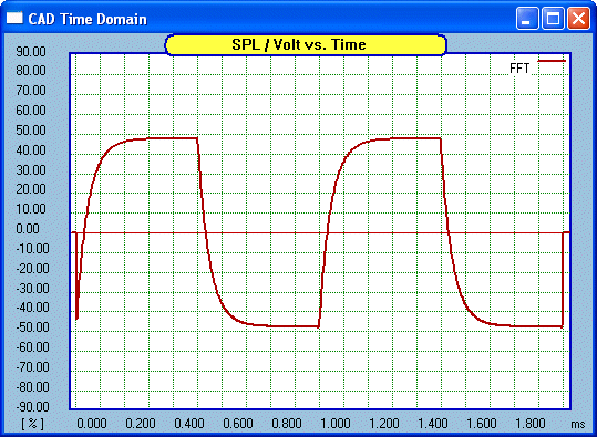
The leading edge has been blunted. Is this not what we
would have expected based on the Treble boost?
Now for Bass boost:

Now for our matching square wave:
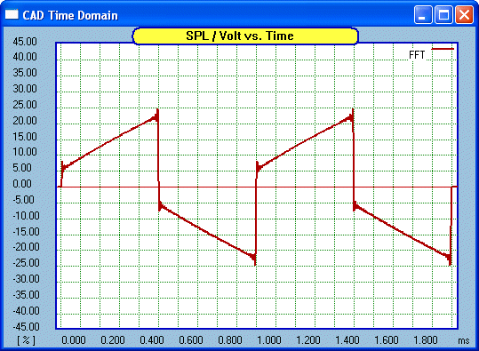
Now the back end of the square wave is elevated. This
should be expected even if not as narrow as the Treble boost (for reasons
not needed here). So Treble boost increases the leading edge whereas
Bass boost increases the trailing edge.
Now for Bass cut:

Now for our matching square wave:
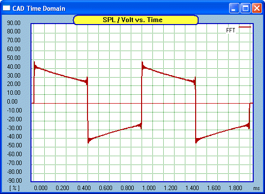
No surprises here, the trailing edge is
suppressed.
Examine the above a bit more and you will see the
pattern. But let us sum up by re-showing our original 1KHz square wave and
add some pointers:
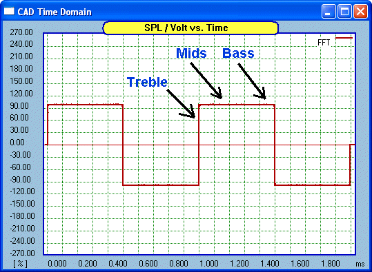
There is a rule of thumb that I use. If you have a
proper square wave with flat top and clear vertical lines, the response is
flat from a decade below and a decade above the frequency of the square
wave, two decades. Hence flat from 100 Hertz to 10KHz. Therefore the
tonal balance would be neutral. Yes, we can look at a square wave
and draw certain conclusions from it.
Now we get to the meat of our discussion. From sine
wave to square wave and now progressing on to the Step Response.
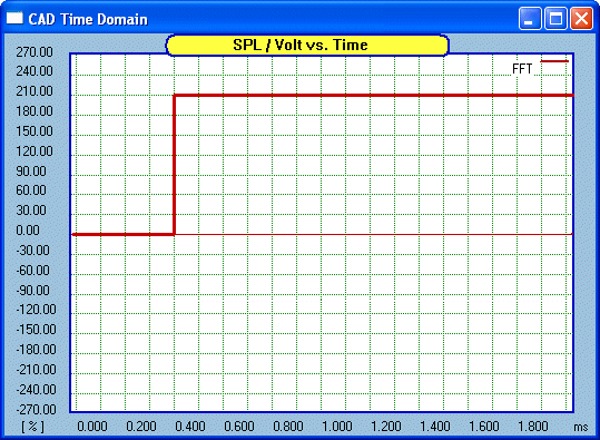
Unlike a sine wave or a square wave, the Step Response
has no frequency. It doesn't cycle up and down but is a single step in one
direction, like a staircase with a single step (I know that doesn't make a
staircase, but you can also think of it as a street kerb). But there is a
similarity with square wave, the front of the step indicates the Treble
response, then as the step progresses it goes through the Mids and then the
Bass.
Here is what our step response looks like and this is
what we will feed through our DUT (remember, Device Under Test):
Some have declared the the Step Response is the single
most revealing test that can be applied when the DUT is a loudspeaker
system. This includes the late John Dunlavy. It is certainly
a most
intriguing test. Note that it is the complete system that must be
tested and at a position that is representative of the expected listening
position would be desirable.
Again, we must point out the obvious:
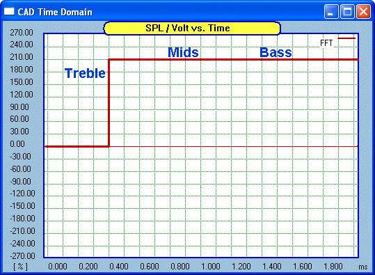
But we can also examine individual drivers and plot
them to see what their exact contribution is. We can also include either the
raw driver or include the crossover. So this is a great multi-level
tool for investigation.
It's The Tweeter Dummy
Oh yeah! It is the Tweeter that is the issue
here, so let us get back on track.
Here is the Step Response of the HDS Tweeter in the
Elsinore box:
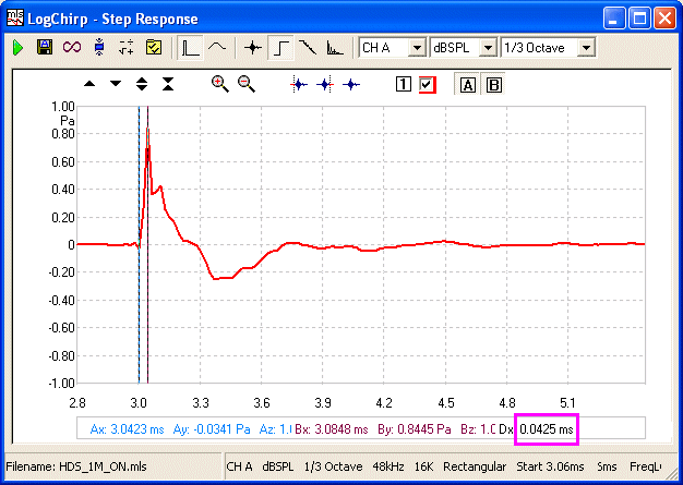
This Step Response of the raw (no crossover) Tweeter
shows its attempt to match the infinitely fast rise time of the step. At the
top of the rise the step flattens out to (theoretically) infinity. But that
flat plateau is the electrical stimuli. But the response picked up by
the microphone is the acoustic response.
We have already established
that there is no acoustic output unless there is motion, and there is motion, but from this point onwards the phase is
reversed.
If you consider what force is
at work, it is simply ambient air pressure; the air has been loaded like
spring and works in reverse.
In the example shown here the rise time is 0.0425mS
(look for the purple box where Clio displays the time difference between the
two markers). We can now invert that (1/0.0000425 = 23529) and it represents
23.5KHz.
Now imagine that our Tweeter was virtually perfect in
the sense it had infinite rise time to match the stimuli:
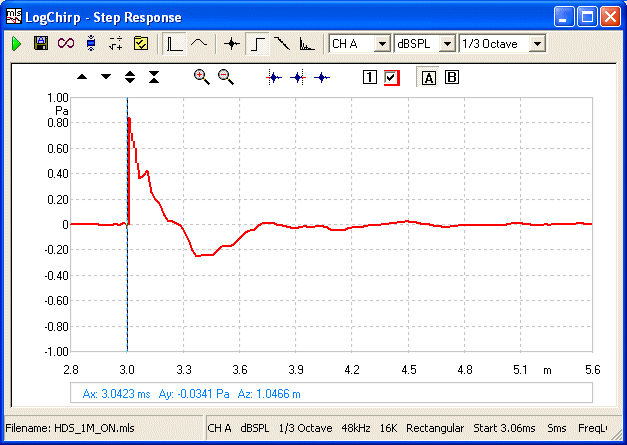
Now inverting infinite will give us an infinite
frequency, now ALL the Tweeter's acoustic output is in the reverse phase.
Now it would make sense to invert the Tweeter's phase:
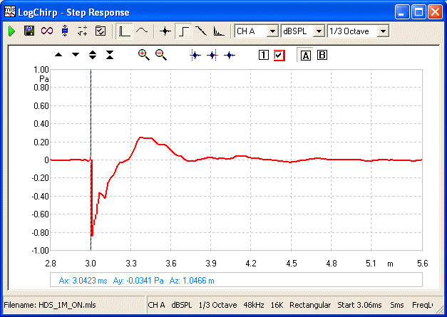
Now where does the acoustic impulse really start?

It starts where the Blue dot
is the marker. There is little difference from this and to this:
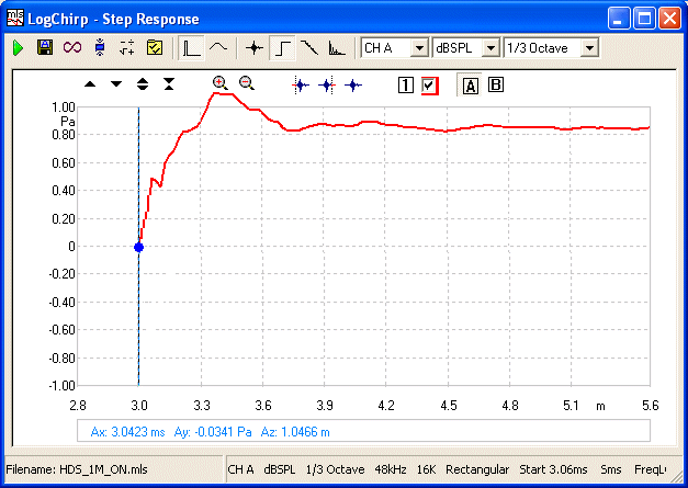
Yes, it starts with the Blue
dot (but allowances needs to be made in the final design). But in reality this is not completely true as we don't have infinite
rise time. But the above in totality demonstrates the point clearly. In the case of the HDS
Tweeter (now Scan-Speak 'Discovery' D2608), the frequencies below 20KHz is dominated by an opposite acoustic
phase.
The Tweeter's acoustic phase
is the opposite to the Tweeter's electrical phase.
There is a precise 180°
relationship.
The faster the
Tweeter's rise time, the greater effect of this scenario.
An infinitely fast Tweeter
has ALL of its useful acoustic output in the opposite phase.
At this point I will revisit some of the points
discussed in Chapter 17. Sorry for the repetition, but Repetition is
the Mother of Retention. As the Tweeter in
question will need a Lo-Pass filter (crossover) and also match up with a
driver handing over from the Midrange, in our case about 3Khz, let us
examine that in some detail.
 Here
is a 2-Way example, where Blue represents the
MidBass and Red is the Tweeter with a
deliberate reversed phase. The bottom of the inverted Red peak and
hence when in time the Tweeter is going positive, is
made to coincide with the beginning of the slower rise time of the Blue
MidBass.
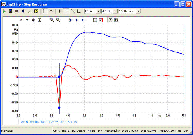
Line Up the Blue dots in time (time
alignment). Both the Tweeter (Red) and MidBass
(Blue) go positive at the same point in time.
Is is extremely important to observe that
there is no output (or very little) from the MidBass during the fast negative inverted
rise time of the Tweeter. Effectively the idea is to get this part of the
Tweeter's output well out of the way
in time, so that the positive outputs of both drivers are in sync.
Some physical alignment of drivers is desired or required to optimise this.
But the window is nowhere near as critical as Butterworth or trying to
vainly match 'acoustic centres' that is hit-and-miss.
That this also allows us to sum at the crossover by 100% is now hardly
surprising. Here we have a clear visualisation explaining why.
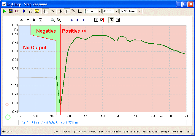
Finally we have the complete system Step Response.
At no point are the drivers working against each other, both
in time and amplitude (frequency), they are perfectly synchronised.
To the left, the green area, we only have output
from the Tweeter. This is the fast rise time of the Tweeter, inverted. It
equates to frequencies well into the top octave and higher and is shown by
other examples in Chapter 17 to be well away from the crossover. On the
right side we have a time coherent
picture even though our Renegade Tweeter is connected electrically out of
phase and it has no 90º Butterworth error. IF we
did connect the Tweeter in phase, then we would have to re-jig
everything and accept the Butterworth phase error and other attendant
problems (did anybody say power response?).
But, because we are still getting the phase right, we are thus able to produce decent square waves at
around 1KHz.

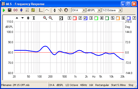
This example is actually a
measured 700 Hertz
Our system minimum phase response confirms this as well (at 2 Metres):
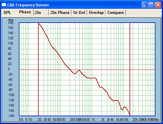
And so does the actual measured system phase response:
Phase Response at 2 Metres - LF accuracy limited to
above 200Hz
I believe a good case has been made here. The advantages of getting
the Tweeter phase right are numerous.
All the benefits are only
available by reconsidering the electrical phase reversal as the most
practical solution available to the designer. The Tweeter will correct its
own acoustic phase.
The above complete system Step Response also confirms all the
conclusions drawn in Chapter 17. The fact that
the impulses of the Tweeter and MidBass are properly synchronised shows that
100% vector summing (at minus 6dB) is a reality and by extension provides a working
solution to the off axis response problems usually caused by MidBass
beaming effects, this bodes well for a more consistent Power Response.
Numerous Benefits
The additional benefits are also better power
handling, especially the Tweeter, lower distortion, again the Tweeter (use a
null filter as used in the Elsinore enhances this further). Lower distortion
also from the MidBass driver as its output is 3 dB lower above (and below in
the case of the Tweeter) the crossover point. Although less output, the
MidBass sums 100% even if considerable beaming is already happening. Less
demand on its bandwidth. There is also less unnecessary current drawn
from the amplifier across several octaves, the impedance and load is easier
to control as no acoustic power is wasted (as opposed to VC heat, but that
is another subject, but VC will still run cooler by some margin). These are
but the highlights...
Physical Alignment of Drivers
The above Step Response was based on an MLS type signal equating to 1
Watt. If the step was increased by two to one, this would require 4 Watts.
The rise time would also be longer, typically 60uS where it was 42uS for 1
Watt. This means a change from approximately 23.5KHz to 16.5Khz.
This leads to the physical alignment of drivers to be
considered. As the time of the Tweeter to reach it maximum in time is
dependant on input stimuli, then it's apparent that the relative time
alignment changes with input. The above examples show that it is only very
high frequencies that are affected. Hence 23.5KHz for 2.83VRMS and 16.5KHz
for four times the power.
The relative slow rise time of
the Midrange driver works to our advantage here. As the Tweeter output
shifts the time relationship, the Midrange driver's output is virtually zero
or at least very low. This means a good size time window exists and that
ultra-critical alignment of drivers is not... well, so critical. This is so
unlike 1st order Butterworth and also helps why the result we get has a much
wider usable window (and much more desirable power response), rather than
the narrow window one must aim at with Butterworth approach. It makes for a
better speaker and an easier job for the designer.
Three-Way Systems
As I have mentioned elsewhere in Chapter 17
the use of Butterworth 1st order below 1KHz is far less problematic as we
deal with drivers that are well within their pistonic range. So for a time
aligned system, consider using Butterworth 1st order as the lower crossover
and the above described approach. Please read Chapter 17
to complete the picture.
Here
ends the story of the Renegade Tweeter Theory. Or does
it...? |