|
OUT OF DATE DATA
!!!
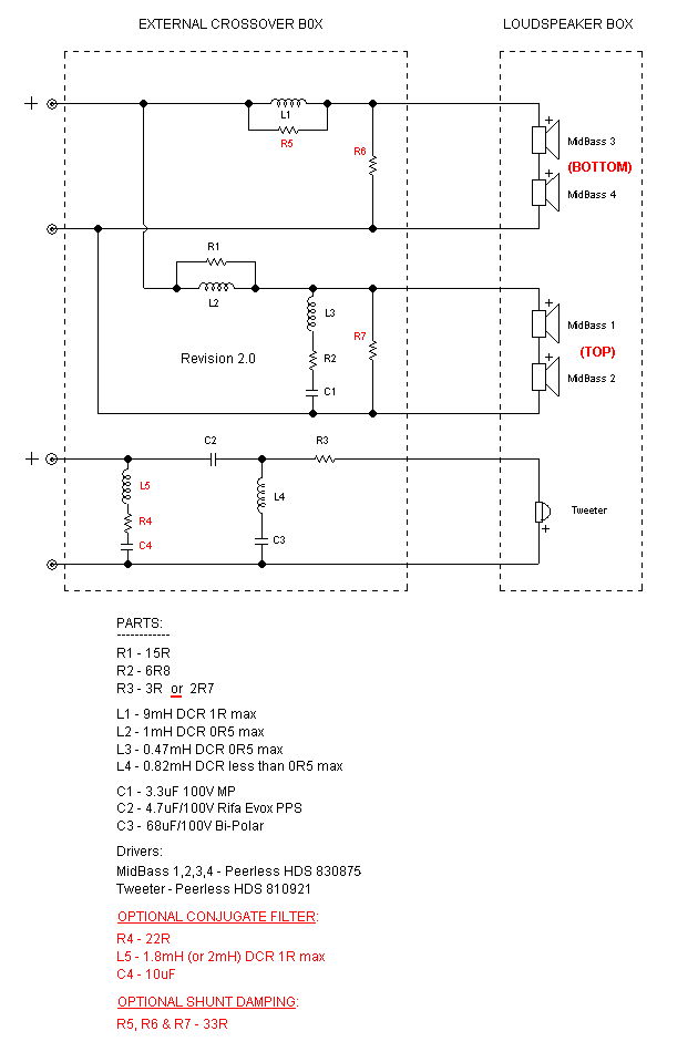
Elsinore Mk 4 (& Mk3) Crossover & Notes
Based on real measurements of Mark 2 rather than
simulation, it was decided that the Step Response as well as box
construction could be simultaneously simplified. The changes are also
easily implemented to Mark 2 already built. Instructions are being developed
here.

Note: Crossover & Values
of Components are Subject to Change - Date 21st September 2007
IMPORTANT: I ended up using 4.5 to 5uF
total for C2, I specified nearest standard value as 4.7uF
For somewhat more energy in the 'presence
region' - use 5.6uF
The new HDS Tweeter is not as flat as the previous XT25,
but it has much lower distortion and superior in every other way. The Mk2
now specifies the use of the Nomex version 830875. This has virtually an
extra dB of sensitivity and the HDS tweeter means we can exploit that and
yet still maintain a nominal 8 Ohm load, something that could not be claimed
with Mk1.
OPTIONAL CONJUGATE FILTER:
This has a dual purpose. First, it flattens out the impedance curve
between 300 Hertz and 1500 Hertz. This means that the source impedance of
the power amplifier is less likely to modulate the frequency response, such
as non-feedback single-ended triodes and push-pull tube amps. Second, since
the electrical first order hi-pass on the tweeter results (as is usual)
negative current just below the crossover, the conjugate filter offsets this
by drawing positive current, and hence the total negative phase angle (load
wise) is reduced to -18° at 2200 Hertz. As the impedance
is a high 9.5 Ohm at this frequency, this is quite a mild load.
Frequency Responses & Other
Measurements

Above: 1 Metre Family of Frequency Responses -
Red ON Axis - Blue OFF
Axis 15° - Brown 25°

Above: 2 Metre Family of Frequency Responses -
Red ON Axis - Blue OFF
Axis 15° - Brown 25°
Because this has a rising response the
optimum listening angle is Blue OFF Axis 15°
where the 2Pi response is better than -/+
2dB 60Hz to 12KHz (ignore microphone proximity effect around 150Hz).

This shows the system impedance and
Pink electrical phase
(using the optional Conjugate Filter). The Blue impedance stays well above 6 Ohm
and hence qualifies as an 8 Ohm speaker system. The lowest phase angle is at
80Hz (-45°) but the Z here is 18 Ohm. The other low is at
2200Hz (a moderate -18°)
and Z is 9.5 Ohm. As stated before, this is clearly an easy load and also suits the use of tube
power amps as the modulation of the frequency response will be mild.
2 Metre Impulse Response (simulated square wave @
500Hertz)

This may surprise a few. There are
not many speakers capable of this kind of result. The
reverse electrical phase does not translate into a lack of flat phase
response until near and above 10KHz. The beauty of this is that we
are able to aim for perfect summing from 1M onward and a large lateral off
axis spread. This is difficult to achieve with so-called in-phase
drivers (believe me, I have tried for many years and it just doesn't work).
The acoustic phase is correct until the top octave is reached.
Because of this, and the time coincident mounting of the drivers, they are
entirely in-phase at the crossover and maintain so over the
whole overlap. Thus the drivers sum 100% all the time unlike conventional
Butterworth which has a 90 phase error and hence susceptible to rippling of
the response.
BUT...
You may think that using a
simulated square wave is cheating, but it is a difficult ask to do a full
measurement as it requires that nearfield response somehow be incorporated.
But an effort was done by going outdoors and minimising reflections and
raising box well off the ground. Instead of 500 Hertz, a realistic and only
slightly higher 700 Hertz proved achievable:

700 Hertz square wave captured at 2 Metres and 15°
Off Axis
This is a remarkable achievement by any standard!
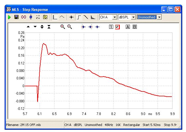
Step Response

Red is the Step Response,
also captured at 2 Metres and 15° Off Axis
Effect of the Conjugate Filter
& with Mark 4 Damping Resistors
with Series
Resistance

RED
represents zero impedance and BLUE is
5
Ohm. The response shape is changed only very little.
Diffraction Control
Two pieces of Felt (see Construction Page for sizes). These helps clean up the response. Use
Felt of
reasonable density (not too light) 6.40mm (8-9mm uncompressed) - or use foam if that is only
available.

Recommended Room Positioning
graphic missing
At the preferred listening position you should be able to
see the inside panels of the speakers (see red dotted line). It pays to
experiment with the width between speakers. The rear of the speakers should
be at least 500mm from the wall.
|