|
< <
BACK TO DIY MAIN PAGE
We have covered a lot of ground, let us leave the more
theoretical behind and deal with more practical matters, like the Power
Supply and critical Wiring.
I think it can be appreciated
that a circuit diagram only tells so much about wiring and especially the
technique that a designer or DIY’ourselfer might employ. Earthing is now
taken for granted as very important not just for best sonics but also to
keep an amplifier from going unstable. The latter is certainly the case
here. A badly wired Gainclone can have all sorts of buzzes and noises, also
the heatsink might feel too warm even though there is no signal passing
through – most certainly a case of oscillations and watch out for your
tweeters!
I certainly have my own ideas,
both practical and intuitively. I think in terms of AC and DC currents
ALWAYS running in loops, and different loops must not interfere with others.
This is difficult to explain in a few words and this won’t be the place.
Critical View of Speaker Return Wiring
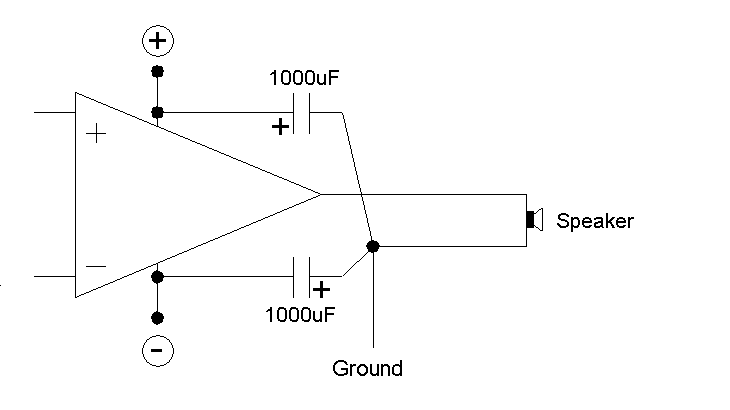
Please look carefully at the diagram below. It is
critical that the load of the loudspeaker is terminated as shown. I can give
you a long and well argued reason for it, but this will have to suffice: All
IC amplifiers are internally compensated at a point in its circuit where its
gain is produced. Across this gain is a small capacitor and at the point it
connects back to acts as a comparator. This 'compares' to something that
must be a signal ground. The problem is that the signal ground is usually
derived from the negative power supply terminal of the IC. At very high
frequencies this can create problems with the return load. The two 1000uF
caps should be mounted close to the positive and negative supply terminals
and there common (ground or 0V) must be where the speaker's load also
returns. If this is not strictly adhered to, then irrespective of
what other ground techniques used, you can expect less than optimum
stability and other undesirable load/cable sensitivities.

The below suggested wiring diagrams
incorporate the above principle. Follow them carefully.
Two Grounds
In our IGC circuits we have TWO
Earths, we will call them “S” for signal and “G” for ground, indeed “G” can
also be called Power Supply Ground or “PSG”.
This is how it is applied
Single Common Transformer:
This is how it is applied for Single Common
Transformer for Left and Right Channels:

OR:
Separate Transformers for Left and Right Channels:

For the NON-tubed version:

The TWO earths can clearly be
seen here, they are the two black round pads. It can also plainly be seen
that the Power Supply uses “G” but the input Signal uses “S”. They are tied
together by a single wire.
Thick lines indicate heavier duty
wiring. One that I found particularly critical is the wire from between the
two 1000uF electro caps (0V) going back to “G”. Use good quality
multi-strand wire with very low inductance.
It is important that IF using the
Tube Version, that it too gets its Signal ground from “S”. So in technique
in the two versions are much the same:

Re the power transformer, follow
the usual recommendations. Some like using separate 160VA toroidals for each
channel (but a single 160VA common for both channel does work and I've tried
it). You can do that or use a common toroidal for both but may then want to
use something like 300VA.
Whatever you do, the Bridge and
1000uF caps must be separate for each channel even if common secondaries
used. So the diagram above must be repeated for each channel. My strong
recommendation is the 1000uF/50V Panasonic FC cap. The Bridge I used is four
10A 100V Schottky Diodes (in TO-220 packages) and make a discrete Bridge.
Here is my suggested Power Supply
– keep in mind I am NOT supplying a PAINT-BY-NUMBERS project, this is for
the serious DIY’ourselfer.
Main Power Supply

Note that I use a feature also
used in the commercial JLTi Hybrid Tube Integrated Amplifier. When power is
connected to the IEC socket the Tube Buffer powers up and stays in Stand-By
mode. The Power Switch then only turns On of Off the Gainclone output stage.
This so-called ‘Permanent Stand-By Mode’ means that when amp is plugged into
AC, make sure that the Power Switch is set to OFF. In this way we avoid rude
noises of the Tube Buffer as it stabilizes.
Tube Buffer Supply:
The 2 x 1000uF/50V may I suggest
that you also use the same Panasonic FC caps here. The 1uF/100V must be a
suitable film type, NOT an electro. I recommend a 30VA Toroidal Tx,
25V-0V-25V. I use four 1A 1000V FRDs as a discrete Bridge. Together with the
Panasonic FC caps, this makes a Split Rail Power Supply, plus 35V and minus
35V.
The Filament Circuit: This can be
powered by a small transformer rated no less than 5VA. The 5R6 1W slows down
the initial filament current, better for long term life.
The rest should be
self-explanatory. Be sure to apply all Power Supply ZERO volts to the “G”
ground, and NOT “S” signal ground.
For NON-Tube version IGC, just
pare down above.
Join Us On
The DIY AUDIO FORUM
< <
BACK TO DIY MAIN PAGE |