|
PLEASE
NOTE - THIS PROJECT ARTICLE IS NOW AN "INTEREST" ARTICLE ONLY
Note that
some things are not up-to-date
"The Linear Current Loudspeaker"
An Introduction

Below is the updated version of the article published by ASoN (Audiophile Society of NSW) .
The Linear Current Loudspeaker - With Near Pure Resistive
Load:
I doubt that you have seen such a
measurement as above.
Blue: Impedance -
Red: Electrical Phase
The usual loudspeakers most of us use, it
is the current that causes the speaker's Voice Coil to move. It
makes inherent sense to use current. Only the edge of the Voice Coil sees
the voltage, but this voltage is not in the magnetic gap. Send voltage
down a line (a conductor if you will) and that voltage will be divided up
along its path by various elements until it reaches zero. Send current
down the same line and the current stays the same all the way
through. That means that the very force that activates the
speaker is constant. Voltage is never a constant.
-----------------------------------------------oooOOOooo-----------------------------------------------
The
Mystery of the Current Mode Amplifier
(Or “The Journey of
the Non-Voltage Amplifier” Part 2 - Part 1
here)
Again I would like to qualify the
above title; we are not so much talking about amplification but rather the
delivery of power to the speakers.
The idea of using
Voltage as a concept of power delivery to speakers is not difficult to
understand, as the voltage signal can be displayed as it is regularly done
on oscilloscopes where we can see with our eyes that the waves conform to
our idea of how waves travel through both electronics and also through
speakers and the air. But using “Current” as the delivery method to
loudspeakers is not so intuitive and trickier to grasp.
But those familiar
with Ohm’s Law, the mystery is at least not quite so great. If the load is 8
Ohm and we send down enough current, the exact same voltage will appear
across the same 8 Ohm Voice Coil. But there is of course now the problem
that if the 8 Ohm is not flat across the whole frequency response
of the speaker, then the voltage will not be flat and neither will
the frequency response.
The loudspeaker
as a system needs to draw linear current at all frequencies at the same time.
But this may be at odds with total current drive. There is no total
solution here, but the compromises involved can still be quite acceptable.
Not clear? We shall deal with this
shortly and see examples that should make it easier. But the point is
clear that the speaker Voice Coil can act as V/I converter, where “V”
Voltage is converted to “I” Current, and do the conversion on the fly and
to avoid this as much as possible is the desired goal.
This
makes compromises more acceptable even with techniques used to flatten
frequency response that may seemingly compromise current drive. When the
current draw is reasonably linear to start with, then there is less to go
wrong as the system's summed current is at least stable. Interestingly
even non-Voltage amplifiers will work better under those circumstances.
Not all will agree with this approach as anything that may be perceived as
V/I conversion is wrong. But 50% (or more) of something is better than
100% of nothing.
We can establish that Voltage amps have low
output impedance, many times lower than the speaker’s impedance, and thus
Current amps have high output impedance relative to that of the
speaker. Also we have what we might call Unity Coupling amplifiers, which is
somewhere in between and usually similar output impedance to that of the
speaker. Single-Ended Triodes generally fit into this category, as does my
JLTi amplifiers and likewise Vacuum State and other
non-feedback designs. So we established the three types of amplifier power
delivery to the speaker; Voltage, and non-Voltage types which are Current
and the third, Unity Coupling.
The key to using non-Voltage
amplifiers is the loudspeaker, maybe even the key to Voltage amps. Not oddly, if a speaker is
truly optimised
for Current operation (as a linear load on the amplifier) it will work with any type of amplifier,
but will work even better with amplifiers with some output impedance.
Hence the key is to have the speaker's
load be as flat and as resistive as possible. So if we have an 8
Ohm speaker, it needs to flat as possible and as close as possible to that
8 Ohm target. A resistor draws the same current at any frequency,
is always ruler flat and likewise for the electrical phase, which is to
say that the current at all frequencies always stays neutral
current, linear current. We may not forget that just as Voltage can be positive and
negative, so likewise Current can be positive and negative.
We prefer neither.
Current that is said to be
positive can also be described as inductive. Current that is
negative can also be called capacitive. Inductance is potentially
non-linear, particularly the internal inductance of drivers is recognised
as such. Capacitance is on the other hand is a more severe load on the
amplifier and we must not combine high capacitive negative phase angle
combined with very low impedance at any particular frequency. Heavy
negative currents should be avoided, alas not always.
Most designers are fairly well
aware of these things. Some will allow the impedance to drop way too low
to my liking and also combine it with too much negative phase angle – but
then they would not think for one moment to use anything but a Voltage amp
capable of large current dumping ability. They have been fed that by convention.
The ideal speaker
should be resistive and as non-reactive as possible. Keep in mind that
inductance (some) and capacitance (a lot) are reactive. So is anything
that creates an uneven frequency response, such as cone resonances,
anything that creates pressure on the cones, such as the box and a myriad
of other things.
Can we combine a resistive load
speaker driven by resistive (high output impedance) amplifiers? Yes, it
has now finally been done and will be able to demonstrate it at ASoN’s
August meeting.
Can you see the beauty of this?
The amplifier now has greater immunity to non-linear reactances. Yet this
is rarely explored. Why? Because it normally
would destroy the frequency response unless we
draw flat linear current at all frequencies.
If you read Part 1
[was an earlier article in
ASoN Newsletter ] you would have
noticed that non-Voltage amps are effectively amplifiers that mimic a
series resistor on the output, Unity Coupling about 4 to 8 Ohm and Current
amp the effective series resistor should be a minimum of five times
higher. It can be done. It will be done, and it was done!
For this reason a new speaker
was developed:
Presenting
The
Linear Current Loudspeaker
This will be the first public
demonstration of the The Linear Current
Loudspeakers. These were
nicknamed SOFF, acronym for Seriously Only For Fun speakers.
But that
name
was provisional.
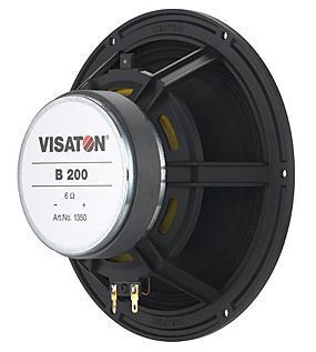
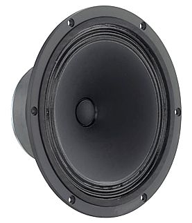
The "SOFF"
speakers are based on the Visaton full-range B200 driver and the Tweeter
is a modified Monacor DF300 with their matching
waveguide. It is a minimum phase 1st order
loudspeaker and ends up with the most amazing resistive load.
The two drivers are clearly shown
in this pic:

The Visaton B200 is German made
and it looks all quality construction.
The Monacor DT300 with
its optional waveguide:
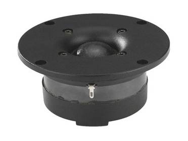
The tweeter is modified by having
the ferro-fluid removed as well as different damping material behind the
dome and using a circular felt with Dacron in the hollow pole piece. Three
layers of BlueTack is used to damp the insides of the waveguide.
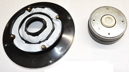
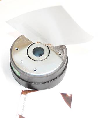
Below shows how the ferro-fluid
was removed from the gap.
The use
of a waveguide is an essential part of this design. It has a significant
effect on the construction of the crossover that lowers the negative phase
angle in the critical upper midrange and lower treble.
Many who take their first look at
this speaker will instantly think, ah horn loaded tweeter. No so quick
please. Waveguides are not horns and don’t even behave like horns.
It has been established that horns tend to maximize impedance transfer and
causes significant High Orders Modes, called HOMs
for short, and this is what characterises the honky horn sound. Waveguides
avoids that and are about constant directivity and avoiding HOMs and the
horn colourations. For those who want to know how Waveguides are different
from horns, may I suggest you read this article:
www.gedlee.com/downloads/Horn%20Theory%20reply.pdf
The Box
People are often fascinated by
what goes inside a speaker box, so here is the internals:
Some would look at this and think “transmission
line” – but I don’t call it that. Besides what is a transmission line? It
seems to describe so many things. So what is this then? I call it an
Aperiodic Damped Line. The reason is simple, the B200 has a high Q of 0.75
and usually a box will push that further up. But this line does the
opposite. It also has a single Q peak in the way a sealed box has, but
much lower peak and hence the added localised damping we shall use
in the Crossover will be that much easier to first model and then
construct. The
damping: Approximately 450gr at the rear and about half that at the front
behind the drivers.
The
Crossover
The crossover is fairly
complex and a total 16 elements make up the total Crossover. It was designed
to have the flattest impedance and electrical phase ever done before. It
is a proper two-way and was optimised to give the following result:

No longer displayed due to commercial
considerations.
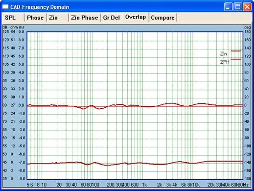
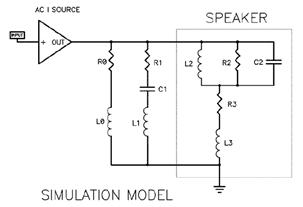
Below is the
actual measured electrical characteristic seen by the amplifier:
The Blue
is the impedance with its scale on the left. It is very flat at 6 Ohm
across 20 Hertz to 20KHz. The Red line is
the electrical phase of the current required by the speaker in degrees;
the scale is on the right. Zero degrees is basically a resistor, so it is
apparent that the above example is as close as you will ever get to having
a speaker act as a pure resistor. Note there is not the usual “saddle”
below 100 Hertz that you get with a bass reflex and neither has the single
peak you get with a sealed box.
Hate to sound like I am blowing my
trumpet, but I do not know of anybody who has achieved such a result. Let
me now show you some samples of typical impedances and phase plots:
Impedance solid line, electrical phase is dotted.
Yes Edgar, this is the Wilson
Sasha speaker as measured by John Atkinson of Stereophile. Note that it
drops down to 2 Ohm and also the saddle centered at near 25 Hertz that
represents the tuning of the bass reflex alignment. The low 2 Ohm is at
least offset as it coincides with close to zero degrees phase impedance at
the same frequency. It is still a heavy load, just look at around 55 Hertz
where 5 Ohm is combined with a large negative phase angle. But I gather
this is rather better plot than the previous model it replaced.
BTW, the peaks above and below the
saddle under 100 Hertz is very well controlled and reveals the 25 Hertz
reflex tuning. I know how Dave Wilson achieved this effect as I also use
it in my latest Elsinore Mark 4 speakers.
Now if you think that the above
looks erratic, then take a look at a typical commercial speaker.
Here the impedance is above the limit of the
graph, certainly not unusual to see plots reach well over 30 Ohms. But
here the designer has at least managed low impedance points and large
negative phase angles not to coincide at the same frequency. Yet this
speaker, and the Sasha, would have difficulties with non-Voltage
amplifiers. The frequency response would deviate significantly. Just how
much will surprise you, so read on.
What these examples prove is that
none of these speakers are resistive. Both the impedance and the
electrical phase jumps all over the place. How can you even say they are 8
Ohm or 4 Ohm or whatever? That seems a rather nominal notion.
But there is a general rule to
follow, determine the lowest impedance and then multiply by 1.4 to arrive
at the nominal impedance. Since the Sasha’s lowest impedance is 2 Ohm, the
nominal impedance is 2.8 Ohm – it is not even close to a 4 Ohm speaker.
Clearly the intent is to use a solid state amplifier capable of that. The
other sample above is the Acoustic Energy AE1 is 4.5 Ohm at 200 Hertz.
Again multiply by 1.4 and we get 6.3 Ohm nominally; cannot be called an 8
Ohm speaker.
The
Ultimate Torture Test
Now let us turn to example of a
locally made commercial speaker, one that is highly regarded and designed
by a friend of mine, available from Len Wallis. Won’t reveal his name
except to say he is a good friend. The modeling info was acquired here
when he brought a sample of this model. What I am about to do to his
speaker system is a torture test that would make any designer cringe.
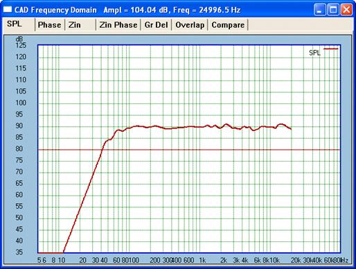
Here is the very flat frequency
response – but it won’t stay that way for long:
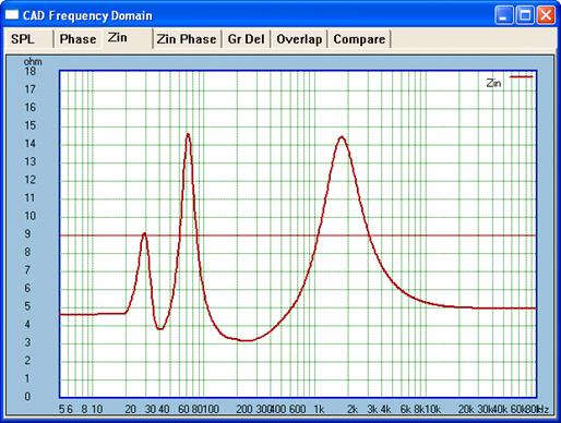
Here is the impedance plot, quite normal as it
goes for a Two-Way:
Here is the electrical phase plot:
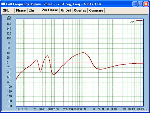
Both above plots are not unusually difficult types
as demonstrated by other examples. For a Voltage amplifier should not be
difficult. The lowest impedance is around 250 hertz, but the phase is near
Zero at that frequency. It’s a reasonably easy load that qualifies as a
nominal 4 Ohm speaker. But we are going to seriously test this and get
this speaker out of its comfort zone.
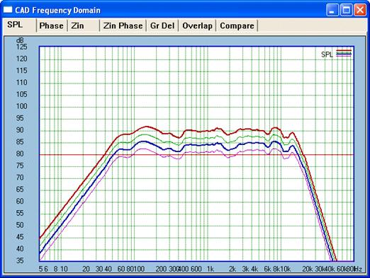
Now let us see what happens when
we drive this speaker from amplifiers that are of the non-Voltage types,
such as Current amp, Unity Coupling amp and compare with a Voltage amp:
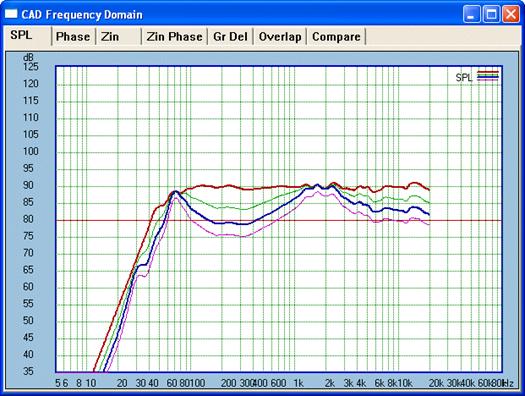
Oh dear! The Red
line is the Voltage amp, the Green line
is Unity Coupling amp and the bottom two Blue
and Violet represents what Current amps
would do.
So that is clearly not acceptable.
But let us now look at what the different non-Voltage amplifiers do to the
electrical phase. This is rather interesting:
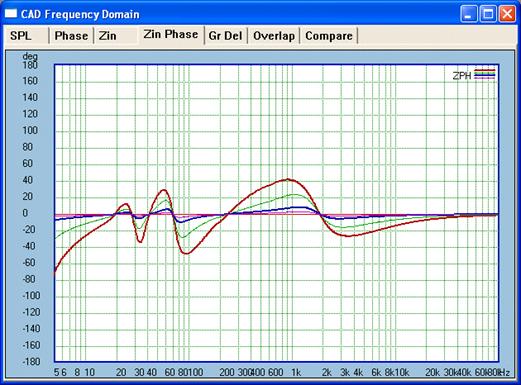
Same colour coding here. Note as
the Red plot is with the Voltage amp which
in theory has near or zero output resistance. It is forced to see the full
negative phase angle whether it likes it or not. The inescapable
conclusion is that the Voltage amp is far more exposed to the vagaries and
sins of the speaker. As we up the virtual series resistance, the amplifier
sees a much flatter negative phase and at 33 Ohm and above this speaker
ends up looking near resistive load, so unlike what the Voltage amp sees.
But, it is a big BUT: The
non-linear impedance, the non-resistive impedance, completely tears apart
the frequency response, and the sample I have shown above is not one of
the worst I could have shown.
The
Linear Current Speaker Undergoes
the Same Torture
OK, here goes. Can I do better or
fall flat on my face? It is now the time to put the new
Linear Current Loudspeaker speaker under
the same microscope. Will I end up cringing as my fellow designer would
cringe with the above example?
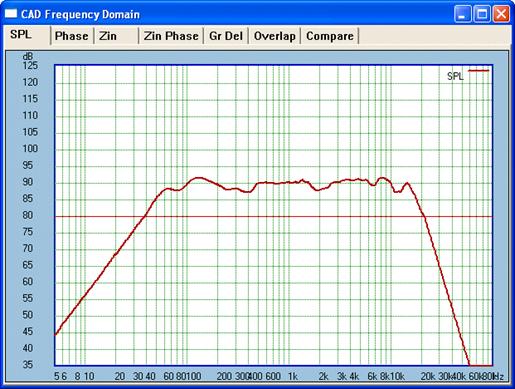
Here goes, first the frequency
response:
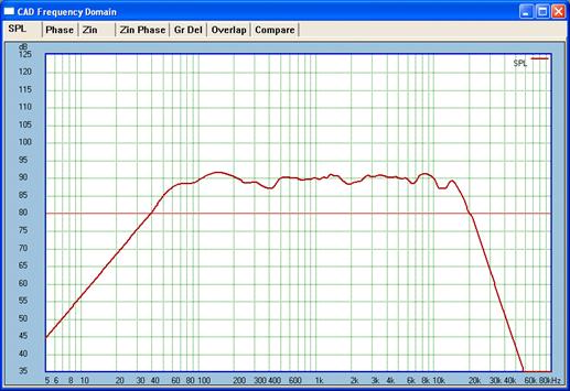
This is quite credible.
Here is the modeled impedance and
phase plot:
The bottom is the impedance and the upper is the
electrical phase plot. This was simulated before the crossover was
constructed and then tested to see if the result would confirm the
modeling. It did.
Now for the impedance and phase
plot, the actual measured result:
Now it gets really interesting, what if we repeat
the above torture test with different types of amps:
This is simply stunning. Right now I have a smile
on my face. Again, if I may repeat, I do not know of anybody else who has
achieved such a result and I have been doing speakers for more than fourty
years. BTW, the electrical phase plot, there is no point showing it as it
just gets flatter, flatter and flattest. At 33 Ohm it is ruler flat.
I will do the ultimate test a
little later using one thousand Ohm.
Now this gives me an opportunity
too good to miss. So on I go on my soap box.
DEMOLISHING A MYTH: HIGH DAMPING FACTOR
The Linear
Current Loudspeaker finally puts the
nail into the “damping factor” coffin. I read a review of an amplifier in
the latest Hi-Fi World where it was extolled for having a damping factor
of over 200. If that is so good, then what happens when we have a damping
factor that is negative.
The problem I see here is that
some people design amplifiers and others design speakers. Never shall the
twain meet. The number of designers who does both is rather
smallish. You have to see both sides of the coin. Who promotes damping
factor? Mostly amplifier makers. What speaker manufacturer talks about the
need for amplifiers with high damping factor? I search my memory bank and
I can’t think of any. Speaker designers think in terms of Voltage and
Current required by their speakers, not so much about damping factor. They
create the load and expect the use of the right amplifier to be able to
match the demand of that load. Simple really. They may well recommend
using Solid State Voltage amps when their speakers have non-linear
impedance and electrical phase. Speaker designers seem to be occupied with
speaker design and let the other mob concern themselves with designing
amps. This is not ideal.
Back to damping factor: When
amplifier’s output impedance is higher than the speaker’s
impedance, the so-called damping factor goes negative. If we were
to follow the damping factor convention, then there would be no speaker
out there that would work satisfactorily with any amp with a
negative damping factor. This is not true.
One designer who wants to
understand both speakers and amplifiers and who has come to similar
conclusions drawn here is Nelson Pass. You may want to read his article
here:
www.passdiy.com/pdf/cs-amps-speakers.pdf
Pass even goes so far to state
that damping factor is often too high and that over-damped bass may
lead to less musically satisfying results. Now here is somebody who
bothers looking at both sides of the coin. Rather than being bothered by
damping factor he says we should aim at a critical damping that
sounds best. He even extols the benefits of low damping factor:
“With
low damping factor, the Fostex [full-range driver] became a totally
different speaker. It suddenly had bottom end response and a better top
end.”
I have never heard an amplifier
designer of note saying that low damping factor could be desirable.
But he did. What gives?
Also, why is the “top end”
improved (but not just that I can attest to)? Just like real estate agents
say the three most important things are location, location and location;
this is a case of immunity, immunity and immunity. The removal of
reactive elements improves everything across the board.
Pass also makes use of conjugal
networks like I do.
What is significant is that critical
damping here is arrived from parallel elements rather than any
damping factor by the amplifier. This is what Pass refers to as
critical damping. This is damping that is localised rather than
coming from an external source supposedly controlling the speaker. Perhaps
the reliance on Voltage amps has not really been helpful to speaker
designers who need to think outside the box.
The primary design goal was
based on the thought that a flat impedance and electrical phase would and
should have both optimum and critical damping. At below 100 Hertz Bass is
where the benefits of damping factor are considered a must. Not here. The
flat impedance and electrical phase in the 20 Hertz to 100 Hertz should
provided the ideal damping, so my antennae told me,
not just a gut feeling, just a right feeling. The results
are definitely proof. I get flat in room response down to 40 Hertz and a 3rd
order roll-off below that. You can definitely hear bass below 40 Hertz,
but the Bass quality struck me as most satisfying. It has speed and
agility as well as a live factor and very out of the box. There are
qualities in the Bass that makes me very happy.
So using the techniques available
we can shunt neutral current in parallel with the load, the
speaker. Properly attended to, this becomes the localised parallel
critical damping of the speaker. Nothing more is needed.
The high
damping factor of the amplifier, basically its low output impedance, may
actually make it difficult and even impossible to apply critical localised
damping. So with Current amps and Unity Coupling amps, it is the speaker
designer who controls the result; the amplifier designer should supply,
not high damping factor, but high immunity.
Will that become a trend? Time to
start one.
Yet the following rules are as
non-violable as laws of nature; they will stand the test of time:
Fact one: Voltage amplifiers,
specifically of the Solid State kind, with significant feedback to
supposedly bolster damping factor, do not have a desirable high level of
immunity.
Fact Two: Classic Single-Ended
Triodes so beloved by many have high level of immunity because they are
Unity Coupling (got that phrase from Lynn Olson) and not Voltage amplifiers. Not just because they are
Single-Ended. Similarly, a properly designed Push-Pull
Triode does likewise.
Fact Three: It does not take a
lot of intelligence to come to the conclusion that the speaker must be
designed to suit the kind of amplifier used. But a speaker with linear
load characteristics incorporating critical localised damping will have
the edge when driven by non-Voltage amps.
The Linear
Current Speaker goes much further
than even what Pass has done and demolishes the reliance on the damping
factor myth, and does so effectively. It will work with any
amplifier. But it will work even better with non-Voltage amps as
the localised critical damping will do its job without being
short-circuited by the low output impedance of a Voltage amplifier.
Speakers with localised damping will work better with non-Voltage amps. It
will work with amps with more than 100 Ohm output impedance.
I want to show you one final
assault on the capabilities of the Linear Current speaker, here is what it looks
like with an amplifier with 1000 Ohm output impedance, that is one
thousand Ohm:
This is as extreme as it gets. So
in this instance, with this speaker the output impedance of the amplifier
is irrelevant. Then the same applies to the damping factor required
by this speaker.
This is a speaker that does not require any damping factor!!!
Damping factor from the amplifier
is completely mute. But the amplifier’s immunity to the
speaker’s reactance is enormous. And you can hear that.
For our upcoming tests at ASoN we
will be guided by Nelson Pass who pointed out that 47 Ohm is adequate for
nominal 8 Ohm speakers to operate in Current mode. We shall use 33 Ohm as
the our speaker is a lower 6 Ohm, not nominal but real. For the Unity
Coupling test we shall of course be using 6 Ohm. We
will also have an actual Unity Coupling tube amplifier, the JLTi KT88.
A Fool
Once, But Not Now
Now for a story that goes back to
circa 1977. I went to the old Pye Australia that used to be in Chester
Hill [Sydney] to buy some Foster 6.5 inch full range drivers. When I picked them up
I was told I ought to get in touch with somebody at Sydney University who
did testing of their speakers.
So I indeed got in touch with him
and also got some computer print-outs from him that showed results from
different box sizes. He asserted that the driver was over-damped for use
in small sealed enclosures and recommended adding a series resistor
as tabulated in his print-outs. I was
truly taken aback by that. Who would recommend adding a series resistor
between the amplifier and speaker? I argued the point with him and even
blurted out at some point, what will happen to the amplifier’s damping
factor? He would have none of it. It was irrelevant as far as he
was concerned.
It took me a long time to realize
that he was right. It was the alignment of the speaker, the actual
final configuration of the speaker that matters. Get that right and
all’s fine.
BTW, the gentleman with whom I had
that argument was none other than Richard H. Small. Maybe that name ring a
bell? When you look up the specs of any speaker you find the Thiele-Small
parameters. Yes, it was that Small I was arguing against, the silly
fool I was.
So the bottom line is this, most
speakers are made in such a way they need a low source impedance to
drive the non-linear impedance and electrical phase. Some are far less
sensitive to this than others, just look at the impedance plot to see if
that is OK. Then judge the effect it has on the alignment of the speaker
system. It is a marriage, a matter of compatibility.
This is a speaker that will
have extreme compatibility unlike any other speaker around. But it will
marry better with amplifiers that have, to use Nelson’s word, low
damping factor. I would go as far as to say none!
We have
but covered the essentials and this amounts to no more
than an introduction.
Joe Rasmussen
At The Cross Roads
joeras@vacuumstate.com
www.customanalogue.com
.
|