Input Module: First it needs to be dismounted. Remove all screws from the back
plate and also three knobs. Remove knobs carefully using something plastic
to lever them of, they are friction fitted only. Behind the knobs are
retaining nuts, use a fine pointed needle nose pliers to remove. The PCB
may not yet come free, it seems that in some cases the thick gasket is
glued and you may need a very sharp blade to cut free.
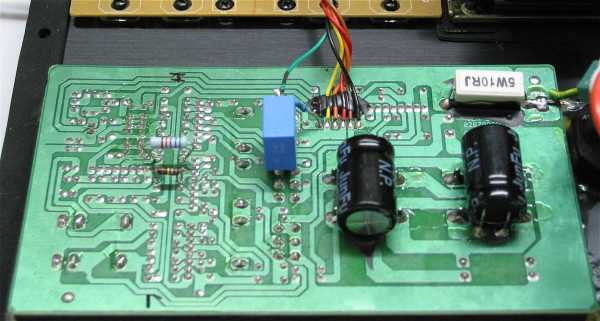
Desolder and remove R26 and R27 from PCB. The PCB is now remounted,
the new R26 and R27 will be fitted on the rear of the PCB. See photo blow.
The new R26 (56K) and R27 (180K) can clearly be seen on the left side of
PCB.
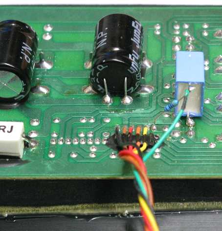
On the Output of Input
Module: Now unsolder the Green Wire that is part of the wiring harness to
Power Amp Module, it is right on the end next to the Yellow wire. Solder 470R to the point where
you removed wire, now wire Green Wire to other side of 470R. Also from
this junction, add 0.33uF to a ground point. Study the photo below
carefully. Please note carefully where the 0.33uF Cap is grounded
on the PC Board.

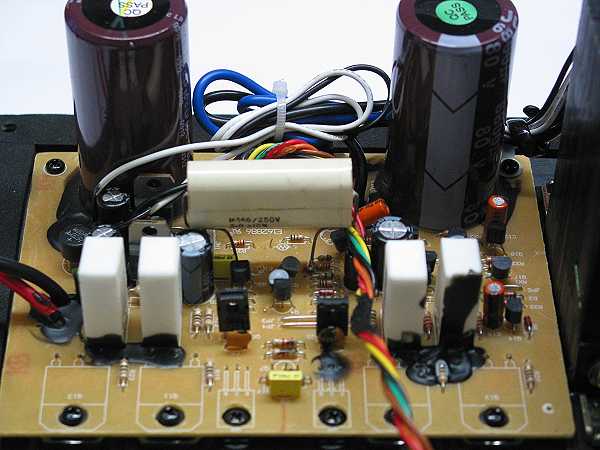
Power Amp Module: Finally, and this is a little tricky, we need to replace the yucky
4.7uF electrolytic used input coupling cap. Cut away old C1 with sharp
pliers, chances are you will destroy it in the process of removing. Next
stage is tricky, wee now need to fit 3.3uF film cap. But this cannot be done unless you would
like to remove the whole module, not recommended. Instead it can be fitted
to other components with ends exposed enough to be soldered to. These are
R1 and R2. Please look carefully at the photo and illustration shown
below. You will need a very fine pointed solder tip, pre-solder the
correct ends of R1 and R2. Also pre-solder the ends of 3.3uF cap, as this
will assist in a tricky job. Do not overheat. Finally use a little bit of silicone glue to
mechanically stabilise cap (not shown).

This requires good soldering
skills
The work is now concluded, please check and
double-check everything, And when you have done that, then triple-check.
Beware that you have no warranty to go back on.
If you have any doubts whether you have the skills, do
not proceed. It may be worthwhile to find a qualified technician,
show him this page and let him proceed. Please understand YOU are
responsible for the end result and YOU have been warned!
See Box Construction Page for detailed Drawings, Cutting Sheet and other
Box Diagrams
See User Setup Page for Operating Instructions.