|
Part Two
[Note: September 2024 - Elsinore Mk6 is current - some things below may be obsolete.]
Preliminary Design Details
In the first instalment,
I disparaged the usual two-way speaker system that
seems to be everywhere. It seems that I am not alone, as I have just picked
up the November 2005 issue of Hi-Fi World. If you thought I was vociferous,
then compare the two statements:
“I do have a problem with the general design of speakers,
most of them are rather ho-hum, and sick of the usual two-way done to death,
just another plain box with small flat baffle, a small port
and fairly conventional crossover. Some of these are done rather better than
others, but there is a bland sameness. They seem to follow too much a
formulaic approach.”
Now for Hi-Fi World:
“Has the
two-way loudspeaker had its day? Marrying a bass/midrange unit with a small
dome tweeter can give good results but this idea has now become part of
ingrained design mentality that is not only uninspiring, it’s limiting
performance…a sea of mediocre two-ways.”
Has somebody been reading
my mail? Find the issue and read Page 47. The main diagram shows the effect
of the acoustic offsets when the drivers are mounted on a
flat
baffle. So while their solution is to change the crossover frequency to a
lower point, they recognise just how difficult that is. So if Muhammad won’t
go to the mountain, then the mountain must go to Muhammad. This will be
our
solution, namely to adjust the physical position so they are equidistant to
where the listener sits.
Now let us get on with
this month’s issues and last month we said we were going to discuss the
following issues, be
sure
to read number 10 as it contains new original development:
1.
Diffraction Loss
2.
High sensitivity vs. electrical
impedance/phase response
3.
Flat off axis (and
hence) total power response
4.
Low thermally induced dynamic
compression
5.
Non-peaky crossovers, theoretical
'perfect transient'
6.
Minimum phase disturbance over a
wide bandwidth
7.
Correct acoustic summing at
crossover frequencies
8.
Pipe Resonances in tall enclosures
9.
Max acoustic power transference
into room
10.
ACOUSTIC
IMPEDANCE DRIVER MATCHING <<<
© Copyright
Joe Rasmussen 2005
11. Quality Drivers
So let us start with the
first one:
Rarely do we hear much on
this topic, but it is so crucial at the first stage of design. Basically, it
has a profound effect on frequency response, overall sensitivity and tonal
balance. In fact, the last two can be traded off against each other. Want
more sensitivity, then simply use less compensation. But what is Diffraction
Loss? Note here the accent should be on loss and something that needs
compensation. Less compensation gives you higher sensitivity, but
that will mean less bass because this is where the loss occurs. Diffraction
Loss (DL) should not be confused with diffraction distortion (DD),
which is not a loss but a series of acoustic discontinuities. I suspect we
shall discuss that (too) later, but let us concentrate on diffraction loss,
DL, and how to compensate for it.
Have you ever seen very
nice frequency response graphs made available by driver/speaker
manufacturers? When in comes to bass/mid drivers, they usually show a fairly
smooth response at least up to 1KHz and hopefully beyond. But these
responses are not recorded from drivers mounted in a box. No, it is usually
on a large panel and in some cases a wall where the speaker facing into a
room that is heavily absorbent like an anechoic chamber. But the most likely
is the IEC Baffle:
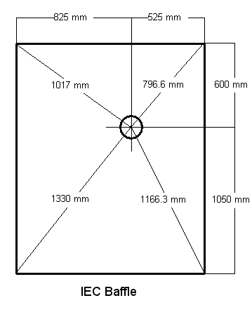
So the driver is flushed
mounted on a large surface area, nothing like the box it is going to end up
in. Basically these panels (or chambers) have little or no DL above 100Hz.
Note also the asymmetry of the mounting of the driver on an IEC Baffle, so
that relative to edges and corners have no repeating dimensions. This means
we are likely to get an even response not affected by Diffraction Loss above
100Hz (DL affects mostly 100Hz up to 1HKz max).
Mounting a driver in a
box, the ideal desirable response might look like this:
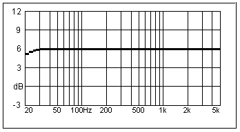
Except for a few minor
dips and peaks, that is what the overall response would look like if the
driver were a good one. This is the response likely in an IEC Baffle, except
the response would die off more rapidly below 100 Hz because of
back-to-front cancellation (the baffle is open, so for the time being
we can ignore that).
But what happens when we
mount the driver in a box:
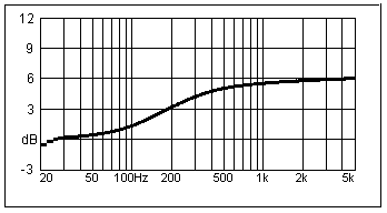
Okay. What is happening
here? For a start, there is a gradual drop in response, which levels out at
–6dB. Here we have a graphic example of DL. It always has a 6dB loss
factor. This is the ideal curve for DL, but in fact it can be a lot more
undulating that the smooth example here (see example further on). But the
response will still start 6dB higher that it levels off on the bass. This is
sometime also called the baffle’s ‘step response’ as it looks like a step in
the response.
But why does it happen
and what modifies the response like that? Let me introduce you two 2Pi and
4Pi concepts. If the panel is infinitely large, then we have a 2Pi response
at all frequencies. All the pressure created in front of the cone is
pushed forward; none of it goes in reverse. With the IEC Baffle, which is
rather less than infinitely sized baffle, the response is 2Pi above 100Hz.
If the baffle was even larger, we could push the 2Pi response even further
down in frequency. But what happens when the baffle area becomes smaller,
then below the 2Pi response becomes 4Pi response. The pressure that was
forced forward now can wrap around the baffle and hence the forward
pressure is reduced roughly by half, which equals 6dB.
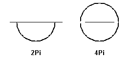
See that in the
illustration, when the wavelength becomes longer it is now able to wrap
around and as such the pressure, and hence volume level, is reduced to half
the amplitude. In the crossover we can apply the following series
compensation network.
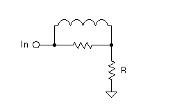
Here R represents the
driver load. The choke introduces a downward slope, is then arrested by the
value of the parallel resistor, which value can be set to 6dB. This would
look as follows:
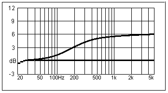
So the top part of the
graph is before compensation and lower is after compensation,
and is now a flat response. This is the affect of compensation, we now have
regained the required flat response but at what penalty? The system
sensitivity has been reduced by 6dB and that means in real terms that it
takes four times the power to maintain the same SPL, which is another
way of saying volume (keep that in mind).
Small mini monitor
speakers with their tiny baffle aligned with small cone, that is a recipe
for low sensitivity and therefore in the 80-84dB range is common. They need
a fair bit of pushing. Our target after compensation will be 88-90dB.
Unfortunately, there are
complications with DL we must touch upon. The nice ‘step’ you see in the
ideal DL slope rarely happens that way. In fact it, the pre-compensated
response can look something like this:
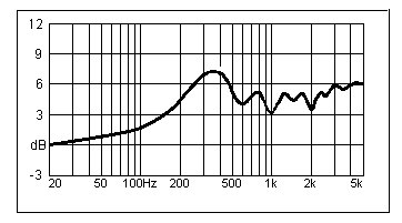
Not pretty. So it seems
that, while the driver may have a flat response, when mounted in a box we
have both DL as well as ripples in the response as some edges of this
rectangular baffle are closer than others, building up pressure at certain
frequencies and not others. Still we can see that 6dB step is still there at
the extremes of the graph. But we also experience some peaks and troughs in
the response. So conceivably, if we can keep the baffle area reasonably
large and rectangular (a round baffle is the worst), as well as using
multiple drivers covering this area can smooth out the response. This
is what we aim to do with the Elsinore.
If we can get the step
down to a low frequency (because of largish baffle area), we may need to use
only 4dB compensation. How much we end up using depends partly on how it
will measure in box as well as listening. But hopefully we won’t
loose the whole 6dB but we may have to be prepared to.
Selecting the driver
affects the sensitivity of our total design, but so do other things. At the
beginning I had in mind a speaker system with high sensitivity and yet also
8 Ohm. There are speakers that boosts the sensitivity by paralleling
drivers, so two 8 Ohm drivers gives us an extra 6dB in sensitivity, but now
being 4 Ohm together, draws twice the current. Now let us use our selected
88dB driver as an example. Put two in parallel, giving us 94dB. Take away
4dB for DL compensation, and we will have a final system sensitivity of 90dB
and four Ohm. So in terms of sensitivity we have gained 6dB, but in terms
efficiency, only 3dB since we have cheated an extra 3db by drawing twice the
current.
But I want to gain the
whole 6dB and to do that I must use four drivers is combined series
and parallel that will give 8 Ohm for the system. I have now gained 6dB in
both sensitivity and efficiency. This makes for a speaker system that
will be easy to drive and also have very large power handling. It will be
compatible with a huge number of amplifiers. Being an 8 Ohm system, we can
also avoid the pitfalls of many expensive speakers, where we have
frequencies where the impedance and the negative phase angle coincide and
place great demands of the amplifier. Our projected system impedance should
not drop below 6 Ohm at any frequency and hence even a moderate negative
phase angle can easily be accommodated. And this is like most only to occur
about 100-200Hz – this will be confirmed when we measure the final
impedance/phase of our completed speaker system.
Most are familiar with
the concept of ‘frequency response.’ But what is not appreciated is that it
is a singular discrete measurement. You look at a frequency response and
you’d have to ask where is the microphone was situated, the height, the
distance and whether it on axis or not etc. The frequency response graph
only shows what the response is where the microphone is located. So in fact
the speaker has many frequency responses, because the response will
change when you change the position of the microphone. So we need to
understand the concept of ‘power’ response. Van Dickason of Loudspeaker
CookBook fame, suggested that it is the off axis frequency response
that indicates whether the power response is flat or not. While that may
take a bit to wrap one’s head around, it does in fact make a lot of sense.
But John Atkinson of Stereophile has taken this idea a step further: The
real frequency response of a loudspeaker is the averaged out response of the
speaker over a 50° arch at the height of the listener (and usually the
height of the tweeter). This way we are able to reconcile both frequency and
power responses.
It has been shown that a
speaker that measures flat on axis but has a droop in the response when
measured off axis (often the midrange start to beam before tweeter takes
over and the total off axis response dies) sounds dull in the upper midrange
and likely sounds like two drivers that do not gel properly. Image placement
and other audible shortcomings issue from poor integrated response in the
power domain.
So how do we deal with
this? We must have a strategy before we can even start. I propose the
following, using low order crossover the drivers must be physically related
to each other at the listening position. Or to put it more plainly, the
distance between the acoustic centres of each driver must be equal distance
to the listener. Our lower crossover is likely to be 300-500Hz where the
wavelength is nearly a meter. Provided the difference is driver offsets are
within 10% of the wavelength of the crossover frequency, we can mount them
on the same flat baffle. So this is no problem with our lower crossover. The
long wavelength solves that one. But if our upper crossover is likely to be
as high as 4KHz, where our wavelength is 85mm, then a few millimetres become
critical, and our error offset should now be well below 10mm. Now the
problem that Hi-Fi World highlighted has been solved. The way to deal with
it is to mount the tweeter further into the cabinet. This is because the
acoustic centres of the 6.5” drivers are much further back than that of the
tweeters; this is what we call their offsets. So we need to
compensate for the difference in offsets and that difference equals
how deep the tweeter needs to be mounted. If you go back to the main box
illustration, you can see the tweeter recess, this needs to be filled with
felt or foam pieces, carefully cut to size minimise diffraction distortion
that can be caused by sharp corners around the recess. This technique was
common in Duntech speakers, so much so that they patented it if using felt
in particular. But the patent was was contested in the market place (not
court) and was not defended.
Since we have now aligned
the acoustic centres of all the drivers, we can now construct crossovers
that have complimentary phase (not the same as absolute phase) and optimise
both our on and off axis responses. The beauty of this method
is that it causes almost zero acoustic interference between drivers (seen as
ripples in the acoustic response as a series of cancellations and summings
leading to a series of peaks and troughs either side of the crossover point)
and also get a nice blending of the two. When we come to constructing the
crossovers, we shall revisit the actual details of this. But the simple fact
is that the summing and blending of the two drivers becomes a great deal
easier this way, the audible driver integration is hugely enhanced and
tweaking the crossover point becomes much more simple when using the ‘sum
and null’ technique explained later.
One of the great enemies
of loudspeaker technology is heat. It goes to the obvious that
speakers are rarely more than 1% efficient, then what happens to the 99%? It
gets expended as heat, and heat in the voice coil has to be dissipated. More
than that, the rise in temperature increases the DC resistance of the voice
coil conductor, whether copper or something more exotic. When a transient is
being fed there will be a sudden increase in that effective resistance which
then erodes the Qe (electrical Q) of the driver, which in turn lowers
efficiency at that moment. So on major transients we now have a
mechanism that causes dynamic compression. How audible is it? It is a
lack of responsiveness and expressiveness. Many like highly efficient
speakers like Lowthers and horns because they have wonderful get-up-and-go
quality. They may not be the ultimate in transparency but they may be the
ultimate in immediacy. They need less power and they suffer less from
dynamic compression.
(Edit, February, 2023:
There are some arguments that says that the thermal change of Re (the
DC resistance of the voice coil) is so slow as to not show up at audio
frequencies and at only very LF, low frequencies.)
In the Elsinore project
we are using drivers that are about 88dB @ 1 meter sensitivity and 8 Ohm. If
we were then to compensate for DL, we would end up with 83dB approx
sensitivity and even though they are a reasonable 8 Ohm, they will need to
be driven hard. Not a solution that excites me.
But here is where the
germ of the main idea of the Elsinore comes in. Four drivers will
gives us 94dB instead of 88dB and still the same 8 Ohm. Hence the 6dB
increase is genuine as it is 6dB increase in efficiency. We can trade
that against DL and hence we have lost nothing.
But more than that, if we
run them together up to at least 300Hz, then above that we can use the two
to cover the mids while gradually rolling off the bottom two drivers. In
effect the top two bass/mids and tweeters become a D’Appolito MTM array.
As these take over, DL will diminish,
making the top two bass/mids working into 2Pi and compensated 6dB for flat
response, while all drivers are combining below 600Hz and so will
compensate for DL and add the required 6dB acoustically where it is needed.
Bingo, a wonderfully simple mechanism to deal with two key problems needing
solutions. So by combining DL and a simple crossover techniques into
multiple drivers, we should, worse case scenario get 88dB @ 8 Ohm and likely
90dB.
What about dynamic
compression, is this being reduced? Absolutely.
Since the gain of 6dB equals four
times less power required for same SPL (volume) and that four drivers share
the thermal load, each driver has to cope with only one sixteenth the power.
The heat and temperature
in the voice coil is several orders lower and dynamic compression
dramatically reduced. This speaker will have excellent dynamics and highly
expressive, but without sacrificing other good things like transparency and
image placement.zH
This topic will be short.
Some crossovers store energy and then release it a moment later. They also
cause smearing in time. So why are they used? For instance, in 3-way
crossovers, the losses in a bandpass filter can be a real problem, so using
peaky crossover we can boost the output. Nice technique on paper, but to be
avoided at all cost. So what are theoretical ‘perfect transient’ crossovers?
Rather than react they give, which is to say they are lossy.
Think of throwing a ball at a wall, it will bounce back. That is reactive.
Now a ball that is able to absorb or loose the impact, hits the wall
and drops straight down.
Generally crossovers that
are as resistive as possible are ‘perfect transient.’ This includes 1st
order and also carefully designed quasi-2nd order crossovers. We must be
able to inject a voltage into the crossover and the voltage must never be
greater on the other side at any frequency, in fact usually less. This is
lossy as opposed to reactive. There are of course higher order crossovers
that achieve the something similar, but these are basically in the
‘critically damped’ crossover camp, these include 2nd and 4th
order L-R types. But the chosen crossover we have chosen here complements
how we will deal with DL and power response solutions. High order crossovers
prevent these solutions. We have also carefully chosen the drivers that are
capable of low order crossovers that creates these possibilities.
There is an obsession
with some to achieve completely flat phase response, a laudable objective,
but maybe more academic than real world. I will aim at something more
practicable that is that phase should be continuous and gradual.
No sudden changes but just a smoothness transition, especially through the
two crossover points. Also the crossover must be minimum phase rather
than absolute phase. This is a much more practical and workable solution.
What is especially good about it is: You know it is going to work
even before you start. It is better to be with a safe bank and have peace of
mind rather than chasing elusive gains.
We shall be using a ‘sum
and null’ technique that allows us to tell whether the two drivers will sum
correctly at the crossover frequency. Here one has to understand the two
concepts of summing and nulling. The two are opposites, but
they can each tell things about the other. By nulling we can tell how well
the two sums. Confused? OK, we need an illustration:
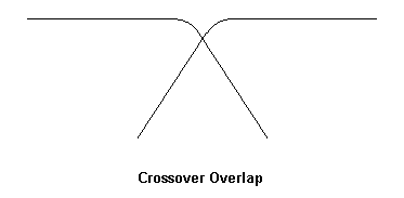
We can see the two
separate drivers responses and the overlap. But the dip at the crossover
point, theoretically –6dB, should disappear when the two drivers sum
together, this is next shown as the darker line:
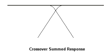
If summed perfectly the
response should completely flat as shown by the darker line, there should be
no ripples that may look like this:
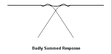
Note that the ripple goes
both above the ideal summed line and also below, hence it looks like a
‘ripple’ in the response. It is caused by poor phase integration and this
kind of effect is common in low order filters. Of course high order filters,
especially 4th, largely avoids this, as the Crossover Overlap is
so small that there is not enough energy either side of the crossover
frequency to cause significant ripple. The only way to get perfect
summing is to stagger the drive units so that the acoustic offsets and
acoustic centres are equidistant at the listening position. Only this way
and careful adjustment of the electrical crossover can achieve virtually
perfect summing throughout the Crossover Overlap. But when that is achieved,
then two important results are superb driver integration and blending, and
consistent off-axis response that result in flat power response through the
Crossover Overlap. When this has been achieved, then as a test we can
reverse the optimum electrical phase and if we have a cleanly summed
response we will get a deep null point:
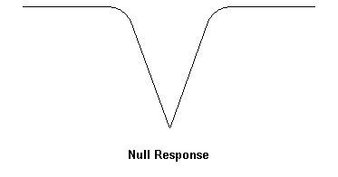
Note that this clean and
deep null response should occur ‘off axis.’
Indeed during the
crossover modelling/construction phase, we can tweak the crossover
components while switching backward and forward between ‘null’ and ‘sum’ and
then adjust for flattest summed response and deepest and cleanest
null. If at the same time we can adjust the acoustic offsets at the same
time, this prevents the ripples and a perfect integration is
possible. And if we are really clever, we will do this with the whole
speaker system off axis at the same time. This will bias the whole
procedure towards power response rather than frequency response.
Basically we must
actually model the crossovers twice. So at the time we capture/measure the
acoustic response of the drivers, we must have two measurements, one off
axis and the other on axis. By making changes to the crossover
modelling we can now observe how the changing values affect both off
and on axis responses.
Also, we must
weigh the off axis response as twice as important as the on
axis. We can now also model a third power response by combining (the
technical term is averaging) these three, 2 times off axis plus one
times on axis, and this allows us also to model final power response.
Now we can see why computers are such a powerful tool, but like all tools
needs to be used intelligently.
Whew! We are getting
nearer the end of this monster instalment. Pipe resonances? Yes, all
cavities will show a pipe resonance when one long dimension dominates. So
they are common in tallish and slim cabinets. Pipe resonances actually show
up clearly in the impedance (Z) graph. Whenever I see a tall speaker, I
cannot wait till I seen the Z plot, and sure enough there will be a wriggle
in around a few hundred Hertz. Here is an example scanned from a magazine
describing a tall slim box driven from a bass/mid in the upper part:
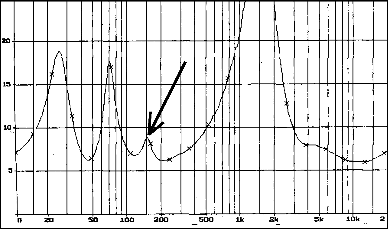
The wriggle in the
impedance plot around 150 Hertz is classic pipe resonance. It cannot be
ignored. Since our chosen box is rather tall and that the height is the
dominant dimension, it is also prone to have a major pipe resonance in a
similar manner. But it is hoped that it will not as we have several drivers
activating the column of air inside the box from four points of the length
of the column. It will be interesting if this will suppress the effect.
Boxes that follow the Golden Ratio, where the height is 1.6 times the width
or depth of the enclosure and the third dimension 1.6th of that,
I have samples showing that boxes following this Golden Ratio have virtually
no vertical resonance. I have spoken to Brad Serhan about this effect
especially as a number of his Orpheus Loudspeaker models are tall slim floor
standers. He is well aware of the effect and also stressed that it was a
mistake to overly damp this resonance as it will kill the sound, so careful
but not excessive damping, largely tuned by ear, is the way to go. In our
case, the effect from being driven from multiple points (four) should mean
that any over damping of the enclosure should easily be avoided.
This is something I
became more acutely aware about twenty years ago. We had an unusual two-way
speaker system based on a Ted Jordan design. The crossover was a low 150Hz
and the two-inch driver covered 150Hz to 20KHz. This was quite a remarkable
feat and it certainly worked. But something was also perceived as lacking.
When the crossover was lifted to around 500Hz it improved dramatically.
There were good reasons for this. The median of the power range of music is
300Hz approx. That is to say that half the energy of music is above 300Hz
and the other half is below 300Hz. This means that the maximum power
generated is centred on the same 300Hz. So the octave below and above, 150Hz
to 600Hz is where most of the energy is emanating from your speaker. To
effectively couple this energy to the room and air we need one rather basic
commodity, a large radiating surface area. Otherwise it may sound
weak and anaemic.
It really is rather
simple, the surface and interfacing with air is a poor acoustic transformer
and a larger surface area means we have a more efficient mechanism for
coupling the energy spectrum and thus the full impact reaching the listener.
The audible benefits are obvious if the drivers chosen do their job (quality
is no substitute) and better defined dynamics. There are of course some
interesting by-products such as smoother transition in terms of the DL.
The combined four 6.5”
drivers all outputs into these two power octaves and have a total radiating
area greater than a single 12” driver. That should do nicely.
The next topic is also related to maximising power
transference into room.
10.
ACOUSTIC IMPEDANCE DRIVER
MATCHING
Please take a good look at the photo of the finished speaker. It looks
like the Tweeter is horn loaded, right? Well, yes and no. What will be
called the Diffraction Wedge (or waveguide) has two purposes. One, to control the
Diffraction Distortion caused by the deep recess the Tweeter in mounted in.
This recess adjust the acoustic centres of the top three drivers to be very
close relative to the listening position. Severe peaks and troughs in the
response would appear without the Diffraction Wedge.
So it is not there for horn loading? Yes it is, but as will be discussed
in detail later when measurements and modelling is described, the horn
loading takes place in the two octaves below the crossover frequency.
From time to time, some speaker researchers and commentators have pointed
to the obvious fact that when we cross over to a small speaker we are
crossing over from a cone (usually) of much larger area. Loudspeakers are
really a kind of multi-transformer, converting electrical energy into
mechanical energy and then to acoustic energy. Both processes are quite
inefficient. We have covered the first part but the latter, converting
motion into acoustic energy, is the focus here.
Clearly a large cone area has a different 'air load' than a tiny (usual 1
inch dome). It is this air load that determines the acoustic impedance.
There is a sudden discontinuity in that acoustic impedance at the crossover
point, especially below the crossover frequency. The off axis
response of the larger cone suffers off axis and if we are using low order
What if we could increase the air load on the Tweeter at around and below
the crossover frequency? We could construct a horn with just the right
dimensions where above the crossover frequency, the horn loading is non-existing.
You want the Tweeter response to be flat here and no horn loading. Coincide
the horn loading to the off axis (as well as overall) response of the
Midrange driver. This means the electrical crossover must be adjusted hand
in hand as well. It becomes a precise integrated whole. Many hours were
spent getting this right - but experiments showed this partial horn loading
was possible in real life and not just a theory.
The horn loading of the Tweeter increase air load and hence increases
the effective are of the radiator.
Changing the air load is the same as increasing
the effective cone/radiating area. We are now adopting the air to do the the
job instead of actual cone area.
Get the ingredients just right and the sonic benefits are substantial.
The physical alignment of drivers, forming a point source, the horn loading
of a specific portion of the Tweeters output, improves driver integration.
The crossover becomes seamless. The kind of benefits claimed for full-range
single driver (Lowther etc) which does not suffer from these discontinuities
(but suffers elsewhere).
Most other conventional multi-way systems sound
thin or lacking a certain substance in the upper midrange, the Elsinore
sounds full and hearty and has this substance where others become largely
vague.
Just quickly. Re horn loading, it is not readily understood that this is
a bandwidth related characteristic. There is always a frequency below and
above where the loading ceases. Also, front loading increases
efficiency, but rear loading does not. We use a short front horn that
has a narrow and precise bandwidth exactly where we need it. The physical
dimensions of the Diffraction wedge sets that bandwidth, not the driver
itself. Extreme horns also colour the sound IMO, but this is avoided here as
the angle of the horn does not even approach 45°. Cup your hand
before your mouth more than 45° and you will hear the effect whilst
speaking. Lessen to less than 45° and it become virtually inaudible.
11. Quality Drivers
Let us not put a too fine a point on this: There is
no substitute for quality drivers. Yes, even the more expensive kinds
may have difficult problems but they usually are also of greater potential.
The drivers we have chosen are of Danish origin and that would have to be
for a speaker bearing the name of Elsinore, a name so famous in Danish
folklore and history.
The four Mk5 Peerless HDS drivers in the chosen
box/alignment is expected to be flat down to 30 Hertz in room. From
2014 onward the Mk6 using SB Acoustics drivers
was born, the first was "NRX" and when that driver was
discontinued, the "MFC"
All different versions use different (but similar)
Crossovers. Make absolutely sure you use the correct Crossover design.
The Tweeter is common from Mk2 onward. It was
originally made for Peerless, but made by Scan-Speak. These days it is known
as the Scan-Speak "Disovery" Tweeter D2608/913000. The design was influeced
by Russsell Storey of Stones Sound Studio. Double-magnets, large rear
chamber that it also creates, the lightest of ferrofluied that is less for
damping than it is to keep the voice coil cooler, and it is 6-8 Ohm and not
the usual 4 Ohm. Despite this, it has high sensitivity/efficiency.
Michael Lenehan (of Lenehan Acoustics) and myself
were the first in Australia to use them as independant designers. In fact I
recommended it to Mike and his venerable ML-1 model has used this tweeter
all these years.
There is a trick to getting ultra-low distortion from
this tweeter. Read on and you will find out in a later instalment.
Next
That is enough to absorb
for now. Next
instalment shall discuss the bass/box alignment in greater detail. The way a
speaker interacts with the room as well as the dynamic versus static
performance choices. It is little appreciated that the above-mentioned 4Pi
response actually reverts to 2Pi plus response at very low frequencies with
a potential 10dB boost (that much is rarely realised, but 7-8dB is certainly
reachable). There are a few dangers lurking here if we are not careful, we
can end up with a mid bass peak and a trough in the response between
100-200Hz. Yikes! Who said that speaker design was supposed to be easy?
Loudspeaker design
involves so many choices, potential vices and optional solutions and few
decisions comes without penalty – I can only think of designing valve output
transformers as a more masochistic art form. Yet it is fascinating to those
who have caught the bug.
Next:
Box Alignment - A Discussion
|